
The Hidden Physics of Flawless Solder Joints
In the modern electronics landscape of 2026, where 0201 and 01005 surface-mount components are standard and high-density multilayer PCBs act as massive heat sinks, relying on a basic unregulated soldering wand is a recipe for catastrophic board damage. The secret to achieving IPC-compliant joints without lifting pads or scorching flux lies entirely in advanced temperature control for soldering iron systems. But not all thermal regulation is created equal. A $30 analog station and a $450 digital workstation both claim to 'control temperature,' yet their underlying engineering dictates entirely different outcomes on the workbench.
This deep dive dissects the architecture of closed-loop thermal feedback, comparing hysteresis versus PID algorithms, analyzing sensor placement physics, and providing a professional calibration protocol to ensure your station is actually delivering the heat it claims.
The Anatomy of the Feedback Loop
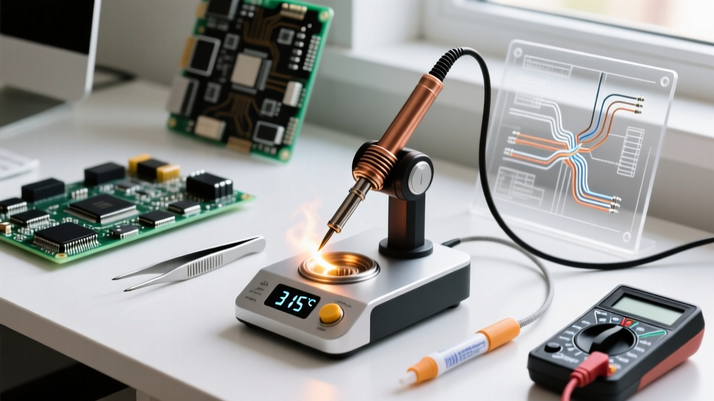
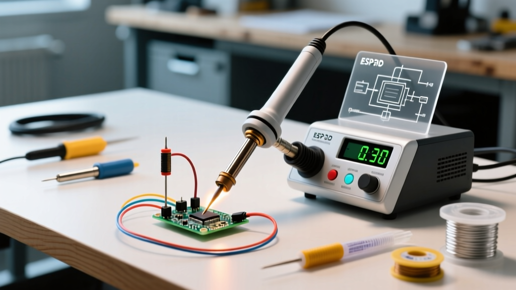
At its core, a temperature-controlled soldering station is a closed-loop system comprising three elements: a heating element (the actuator), a thermal sensor (the input), and a microcontroller (the brain). When you set your station to 350°C, the microcontroller reads the sensor. If the tip is at 300°C, it sends current to the heater. However, how it sends that current defines the quality of the tool.
Hysteresis vs. PID: The Control Loop Showdown
Older or budget-friendly stations (like the classic Hakko 936 clones) utilize hysteresis control, often called 'bang-bang' control. The heater is either 100% ON or 100% OFF. If the target is 350°C with a ±10°C hysteresis band, the heater blasts at full wattage until the sensor reads 360°C, shuts off, and waits until the tip drops to 340°C to fire again. This causes constant thermal cycling, leading to tip oxidation and uneven wetting.
Modern professional stations employ PID (Proportional-Integral-Derivative) algorithms. As outlined in Omega Engineering’s technical guide on PID controllers, this method calculates the exact amount of power needed to reach and maintain the setpoint, modulating the duty cycle continuously. The 'Integral' term is particularly crucial for soldering; it detects when a large ground plane is stealing heat (thermal droop) and aggressively ramps up power to compensate before the tip temperature actually falls below the threshold.
| Control Metric | Hysteresis (Bang-Bang) | PID (Proportional-Integral-Derivative) |
|---|---|---|
| Power Delivery | Binary (100% ON / 100% OFF) | Variable PWM Duty Cycle |
| Thermal Overshoot | High (often +15°C to +25°C) | Minimal (<2°C with proper tuning) |
| Recovery from Thermal Shock | Slow (waits for lower threshold) | Instantaneous (predictive ramp-up) |
| Typical Market Price (2026) | $30 - $90 | $120 - $600+ |
| Best Use Case | Through-hole, heavy gauge wire | SMD, BGA, thermally dense PCBs |
Sensor Architecture: The Bottleneck of Thermal Mass
The most sophisticated PID algorithm is useless if the sensor is physically isolated from the working end of the tip. This is the primary differentiator between mid-tier and top-tier stations.
- Wand-Embedded Sensors (The Legacy Approach): In systems like the Hakko FX-888D, the thermocouple is located inside the ceramic heater wand, separate from the removable tip. Heat must transfer from the heater, through an air gap, into the steel tip, and out to the solder. When the tip hits a cold copper pour, the tip temperature plummets, but the wand sensor remains hot. The PID controller doesn’t realize the tip is cold until the chill travels back up the steel shaft—by then, you have a cold joint.
- Tip-Embedded Sensors (The Modern Standard): Premium ecosystems like the JBC T245 handle or Weller RT Micro series integrate the thermocouple directly into the very tip of the consumable. The sensor is literally millimeters from the solder joint. When thermal theft occurs, the station detects the millivolt drop in the thermocouple within milliseconds, triggering a massive current dump from the 130W+ transformer to recover the temperature in under 1.5 seconds.
Step-by-Step Calibration Protocol
Even a $500 JBC CD-2BE station requires periodic verification. Drift in the thermocouple’s resistance can cause a displayed 350°C to actually be 320°C at the tip. Professional labs calibrate using a dedicated tip thermometer, such as the Hakko FG-100B (approx. $165), which uses a specialized K-type thermocouple with a flat, low-thermal-mass sensor pad.
- Prep the Sensor: Apply a tiny dab of high-temperature thermal paste or fresh liquid flux to the FG-100B sensor pad to eliminate air gaps and ensure accurate thermal transfer.
- Stabilize: Set your station to 350°C and let the tip idle in the holder for 3 minutes to reach absolute thermal equilibrium.
- Measure: Press the tip firmly but gently against the sensor pad. Wait for the reading to stabilize (usually 4-6 seconds).
- Calculate Offset: If the station reads 350°C but the FG-100B reads 342°C, your offset is -8°C.
- Apply Correction: Enter the station’s hidden calibration menu (consult your specific manual for the button combination) and input the +8°C offset to align the microcontroller’s PWM mapping with reality.
Expert Warning: Never calibrate a station using an infrared (IR) thermal camera. Soldering tips are highly reflective and polished; IR cameras will bounce ambient room heat off the tip, yielding wildly inaccurate readings that are often 40°C to 60°C lower than the actual surface temperature.
Alloy-Specific Thermal Profiling and Standards
Setting the correct temperature is not about 'more heat equals better flow.' It is about matching the thermal profile to the specific metallurgy of your solder alloy while respecting industry limits. According to the IPC J-STD-001 requirements for soldered assemblies, thermal excursion times and peak temperatures must be tightly managed to prevent intermetallic compound (IMC) overgrowth, which makes joints brittle.
Furthermore, the NASA-STD-8739.3 workmanship standard emphasizes that excessive tip temperatures accelerate flux burnout, leading to oxidized, disturbed joints that fail vibrational testing.
2026 Baseline Temperature Matrix
| Solder Alloy | Melting Point | Optimal Iron Setpoint | Dwell Time Limit |
|---|---|---|---|
| Sn63/Pb37 (Leaded) | 183°C | 315°C - 330°C | 2 - 4 seconds |
| SAC305 (Lead-Free) | 217°C | 350°C - 370°C | 2 - 5 seconds |
| Sn42/Bi58 (Low Temp) | 138°C | 220°C - 240°C | 1 - 3 seconds |
The Edge Case: High-Thermal-Mass Ground Planes
When dragging a SAC305 joint across a 12-layer motherboard with internal copper pours, a standard 70W PID station will suffer from 'integral windup.' The algorithm realizes it cannot maintain 360°C and maxes out the PWM duty cycle, but the physical wattage is insufficient. The tip stalls at 240°C, resulting in a frosty, disturbed joint. In these edge cases, the solution is not to turn the dial to 420°C (which will instantly oxidize the tip plating and delaminate the PCB pad). Instead, you must increase the thermal mass of the tip (switching from a micro-pencil to a heavy bevel or chisel tip) or utilize a high-wattage station (150W+) that possesses the raw electrical headroom to sustain the PID demand without stalling.
Conclusion: Precision is Profit
Mastering temperature control for soldering iron equipment is the dividing line between amateur repairs and professional manufacturing. By understanding the limitations of hysteresis controllers, investing in tip-embedded sensor architectures, and rigorously calibrating against known K-type standards, you eliminate the variables that cause latent field failures. In an era where a single ruined BGA pad can scrap a $2,000 prototype board, the ROI of a precision PID-controlled station pays for itself on the very first complex assembly.