
Beyond the 350°C Myth: The Thermodynamics of Soldering
Ask any hobbyist or junior technician what temperature a soldering iron should be, and you will almost invariably hear "350 degrees Celsius." While this serves as a passable baseline for general-purpose through-hole work with standard leaded solder, it represents a fundamental misunderstanding of thermodynamics. The true question is not merely what the dial on your station reads, but rather what thermal profile a specific joint requires to achieve proper metallurgical wetting without damaging the substrate.
In modern electronics assembly, treating your station's dial as a static, one-size-fits-all setpoint is a recipe for destroyed pads, oxidized tips, and latent cold joints. To determine the exact temperature your iron should be set to, you must evaluate three intersecting variables: the melting point of your specific solder alloy, the thermal mass of the target joint, and the thermal recovery rate of your soldering station.
Core Temperature Matrix by Solder Alloy
The baseline rule of thumb established by organizations like IPC Standards is to set your iron tip temperature approximately 130°C to 150°C above the liquidus (melting) point of the solder alloy. However, as we navigate the component landscape of 2026, the variety of specialized alloys requires a more nuanced approach.
| Solder Alloy | Composition | Melting Point (Liquidus) | Ideal Tip Temperature | Primary Use Case |
|---|---|---|---|---|
| Sn63/Pb37 (Eutectic) | 63% Tin, 37% Lead | 183°C | 315°C - 340°C | Prototyping, vintage repair, aerospace (exempt) |
| SAC305 | 96.5% Sn, 3% Ag, 0.5% Cu | 217°C - 220°C | 350°C - 380°C | Standard RoHS commercial manufacturing |
| Sn100C | 99.3% Sn, 0.7% Cu, Ni, Ge | 227°C | 360°C - 390°C | Wave soldering, heavy-duty lead-free joints |
| Sn42/Bi57/Ag1 | Tin, Bismuth, Silver | 138°C - 140°C | 240°C - 270°C | Low-temp SMD rework, heat-sensitive flex PCBs |
| Sn10/Pb90 (High Temp) | 10% Tin, 90% Lead | 275°C - 302°C | 400°C - 420°C | Die attach, high-temp environments, sequential soldering |
Expert Insight: If you are working with Bismuth-based low-temperature alloys, never use an iron that has been previously set above 300°C without thoroughly cleaning the tip. Residual high-heat oxidation will prevent the low-temp solder from wetting, leading to severe beading and cold joints.
The Thermal Mass Variable: Why the Dial Lies
Understanding what temperature a soldering iron should be requires understanding thermal mass. A 0402 surface-mount capacitor on a signal trace has incredibly low thermal mass. Conversely, a D2PAK voltage regulator soldered to a 4-layer PCB with internal ground planes acts as a massive heatsink.
Low Thermal Mass (Fine Pitch ICs, 0402/0201 SMDs)
For micro-components, the iron should be set to the lower end of the alloy's acceptable range (e.g., 320°C for SAC305). Using a micro-pencil tip (like the Weller RT1) at 400°C on a 0.5mm pitch QFP will instantly delaminate the FR4 fiberglass and lift the copper pads due to rapid, localized thermal shock.
High Thermal Mass (Ground Planes, Thick Wire, Large Connectors)
When soldering a 12 AWG wire to a massive ground lug, a common amateur mistake is to crank the station up to 450°C to force the solder to melt. This is catastrophic for your equipment. At 450°C, the flux core vaporizes instantly before it can clean the oxidation, and the iron plating on your tip will undergo rapid pitting and degradation.
The Correct Approach: Keep the temperature at a safe 380°C, but drastically increase the thermal mass of the tip. Swap your fine chisel for a heavy bevel or a massive wedge tip (such as the Hakko T18-D32). The larger copper core stores more thermal energy, transferring it into the joint faster than the PCB can dissipate it, achieving equilibrium without requiring destructive heat levels.
Active vs. Passive Thermal Recovery Rates
Not all soldering stations are created equal. The temperature you set on the dial is only the idle temperature. The moment the tip touches a cold copper pad, the temperature plummets. How fast it recovers dictates your actual working temperature.
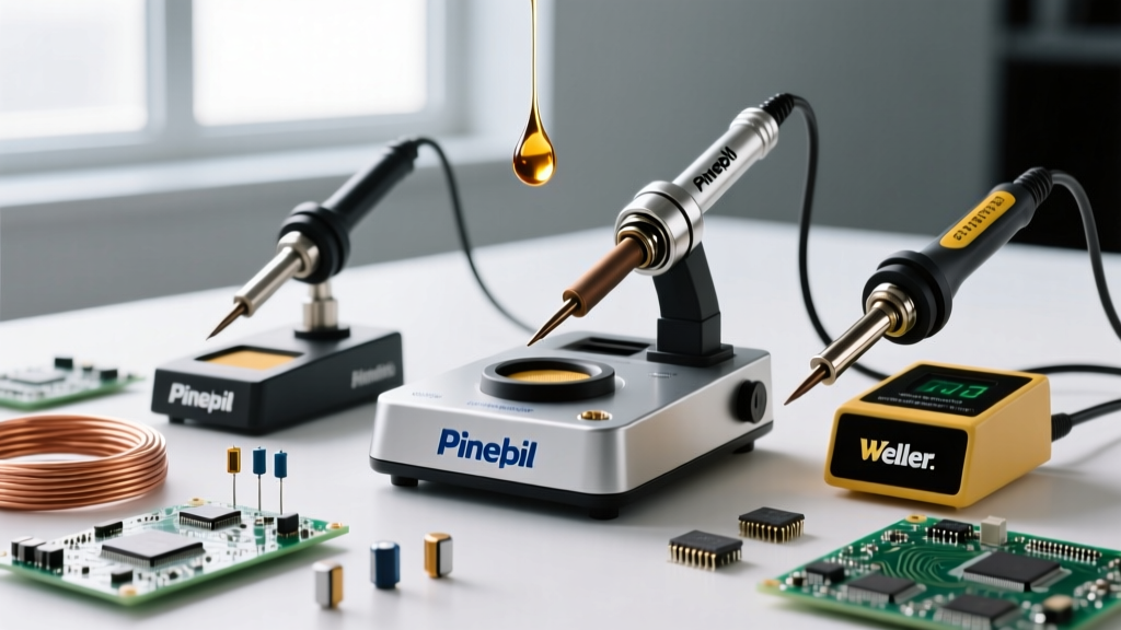
- Conventional Ceramic Heaters (e.g., Weller WE1010NA, ~$115): The heater is separate from the tip, connected via a metal shaft. Thermal transfer is relatively slow. You often need to set the dial 20°C to 30°C higher to compensate for the thermal lag during heavy joints.
- Advanced Cartridge Systems (e.g., JBC CD-2BE, ~$595): The heating element is integrated directly inside the copper tip cartridge. Because the thermal mass of the heater and tip are unified, recovery is nearly instantaneous. With a JBC station, you can safely run the dial 30°C lower than a conventional station and still achieve superior wetting on heavy ground planes, vastly extending tip life and protecting sensitive silicon dies.
Preheating: The Secret to Lower Iron Temperatures
If you are asking what temperature your iron should be for a multi-layer board with heavy copper pours, the answer might be "lower than you think," provided you use a preheater. By utilizing a bottom-side PCB preheater (like the Quick 853A, ~$130) to bring the entire board ambient temperature up to 120°C - 150°C, you drastically reduce the thermal delta.
When the board is already at 150°C, your soldering iron only needs to supply enough energy to bridge the remaining gap to the solder's liquidus point. This allows you to run your iron at a gentle 330°C for SAC305, completely eliminating the risk of pad lifting, barrel cracking in vias, and thermal damage to adjacent BGA components.
Troubleshooting Thermal Failures
According to guidelines outlined in the Adafruit Guide to Excellent Soldering and Hakko's Soldering Fundamentals, visual inspection of the joint and the tip will immediately tell you if your temperature profile is incorrect.
1. The Joint is Dull, Grainy, or Balled Up (Cold Joint)
- Cause: The iron temperature was too low, OR the thermal mass of the tip was too small for the joint, causing the tip temperature to crash below the alloy's liquidus point during contact.
- Fix: Do not immediately increase the dial. First, add liquid flux and switch to a wider, heavier tip. If the problem persists, increase the station temperature in 10°C increments.
2. The Solder Balls Up and Refuses to Wet the Pad
- Cause: The iron is too hot. The flux has vaporized and burned off before it could remove the oxidation from the copper pad, leaving a barrier that the molten solder cannot penetrate.
- Fix: Clean the pad with isopropyl alcohol, apply fresh no-clean or rosin flux, and lower your iron temperature by 20°C.
3. Rapid Tip Blackening and Pitting
- Cause: Running lead-free alloys above 400°C for extended periods. The iron plating on the tip oxidizes and dissolves into the tin alloy, exposing the raw copper core, which will quickly be eaten away by the solder.
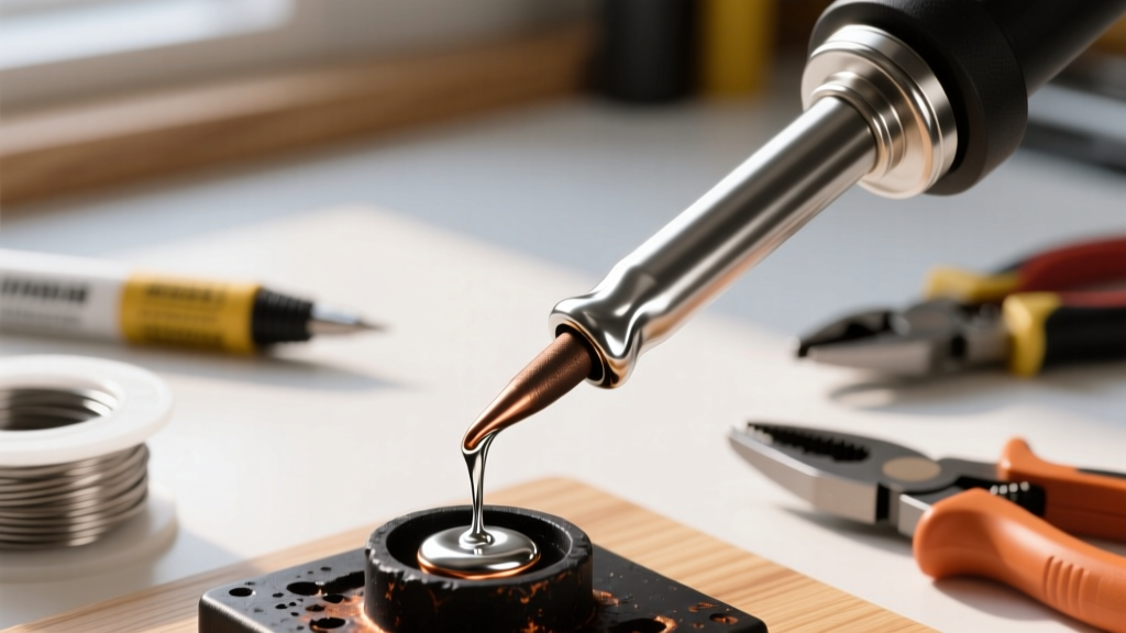
- Fix: Never leave a lead-free iron idle at working temperature. Use the station's sleep/standby function to drop the tip to 150°C when not actively soldering. Always keep the tip tinned with a generous blob of solder when powering down.
Final Verdict on Temperature Selection
There is no universal magic number. To master your craft, you must stop viewing the soldering iron as a simple heat source and start viewing it as a dynamic energy delivery system. Match your baseline dial setting to the specific alloy's liquidus point plus 130°C. From there, modulate your tip geometry and station technology to handle the thermal mass of the joint. By respecting the thermodynamics of the materials involved, you will produce IPC-compliant, mirror-finish fillets while ensuring your expensive tips and delicate PCBs survive the process intact.