
The Science of Heat Transfer in PCB Assembly
Finding the optimal soldering iron temperature for electronics is not a simple matter of turning a dial to a universal number. It is a complex thermodynamic negotiation between the heating element, the tip geometry, the solder alloy, the flux chemistry, and the thermal mass of the printed circuit board (PCB). In 2026, with the industry almost entirely transitioned to lead-free alloys and high-density interconnect (HDI) boards, understanding the physics of your solder joint is critical for reliability.
According to the IPC J-STD-001 standard for soldered electrical and electronic assemblies, the goal is to achieve proper wetting and intermetallic compound (IMC) formation without exceeding the thermal degradation limits of the components or the FR-4 laminate. The temperature displayed on your soldering station is the tip idle temperature, not the temperature of the solder joint itself. When a 350°C tip touches a copper ground plane, the localized temperature at the joint interface can instantly drop below the solder's liquidus point, resulting in a cold joint if the station lacks the thermal recovery to compensate.
Soldering Iron Temperature Matrix by Alloy and Component
The most common mistake hobbyists and junior technicians make is applying a single temperature setting to an entire project. The ideal soldering iron temperature for electronics must be dynamically adjusted based on the solder alloy's melting point and the thermal mass of the target pad.
| Solder Alloy | Melting Point (Liquidus) | Target Component | Ideal Tip Temperature | Max Dwell Time |
|---|---|---|---|---|
| Sn63/Pb37 (Leaded Eutectic) | 183°C (361°F) | Standard Through-Hole (TH) | 300°C - 320°C | 2.0 - 3.0 seconds |
| Sn63/Pb37 (Leaded Eutectic) | 183°C (361°F) | 0805 / 0603 SMD | 280°C - 300°C | 1.5 - 2.0 seconds |
| SAC305 (Lead-Free) | 217°C - 220°C (422°F) | Standard Through-Hole (TH) | 340°C - 360°C | 2.0 - 3.0 seconds |
| SAC305 (Lead-Free) | 217°C - 220°C (422°F) | High Thermal Mass / Ground Planes | 370°C - 380°C | 3.0 - 4.0 seconds |
| Sn42/Bi58 (Low-Temp Bismuth) | 138°C (280°F) | Heat-Sensitive Sensors / Flex PCBs | 220°C - 240°C | 1.5 - 2.0 seconds |
Note: Dwell time is the total time the iron is in contact with the pad and lead. As highlighted in the SparkFun through-hole soldering tutorial, exceeding 4 seconds on standard pads risks delaminating the copper from the fiberglass substrate.
Hardware Deep Dive: PID Controllers vs. Thermostatic Regulation
To maintain the correct soldering iron temperature for electronics, modern stations utilize different control topologies. Understanding your hardware's architecture dictates how you should set your temperatures.
1. Closed-Loop PID Control (e.g., Pinecil V2, Hakko FX-951)
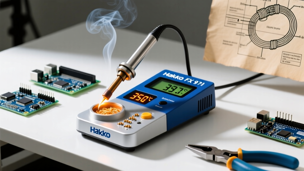
Proportional-Integral-Derivative (PID) controllers sample the thermocouple hundreds of times per second, applying pulse-width modulation (PWM) to the heating element. The Pinecil V2 (retailing around $26 in 2026) uses a RISC-V BL706 chip to run advanced PID algorithms. When the tip hits a cold ground plane, the PID algorithm detects the rapid temperature derivative (the rate of drop) and immediately floods the heater with maximum current before the tip temperature actually bottoms out. This allows you to run a lower baseline temperature (e.g., 330°C for SAC305) while still achieving flawless wetting on heavy planes.
2. Integrated Cartridge Systems (e.g., Hakko FX-951, JBC CD-2BQE)
In premium stations like the Hakko FX-951 (~$230) or JBC systems (~$500+), the heating element and the temperature sensor are integrated directly into the tip cartridge. This eliminates the thermal lag caused by the air gap and mechanical friction found in traditional sleeve-style tips. Because the sensor is millimeters from the working edge, these stations offer near-instantaneous thermal recovery, making them the gold standard for mixed-technology boards where you transition from a tiny 0402 resistor to a massive DPAK power regulator in seconds.
3. Traditional Thermostatic / Ceramic Heater (e.g., Weller WE1010)
Stations like the Weller WE1010 (~$120) use a ceramic heater with a separate thermocouple sensor embedded near the tip base. When the temperature drops below the setpoint, a relay or solid-state switch turns the heater on until the threshold is met. Because of the physical distance between the heater, the sensor, and the tip edge, these stations experience "thermal overshoot" and slower recovery. To compensate for this lag when soldering heavy joints, technicians often have to artificially increase the dial temperature by 15°C to 20°C above standard recommendations.
The Intermetallic Compound (IMC) Layer: Why Too Hot is Fatal
A common misconception is that a hotter iron melts solder faster and is therefore better. In reality, excessive heat destroys the mechanical integrity of the joint via the Intermetallic Compound (IMC) layer.
When molten tin contacts a copper pad, a metallurgical reaction occurs, forming a Cu6Sn5 intermetallic layer. This layer is what physically bonds the solder to the PCB. According to reliability studies referenced in Adafruit's Guide to Excellent Soldering and IPC workmanship standards, the optimal IMC thickness is between 1 and 2 micrometers.
The Thermal Danger Zone: If your soldering iron temperature for electronics is set too high (e.g., 400°C+ for prolonged periods), the Cu6Sn5 layer grows rapidly, exceeding 5 micrometers. This thick IMC layer is highly crystalline and extremely brittle. Under mechanical stress or thermal cycling, the joint will fracture along the IMC boundary, leading to catastrophic field failures that are invisible to the naked eye.
Visible Symptoms of Thermal Abuse
- Flux Burn-Off: Rosin-based (RMA/RA) and no-clean fluxes activate between 150°C and 180°C. If the iron is too hot, the flux vaporizes instantly before it can reduce the copper oxides, resulting in de-wetting and solder balling.
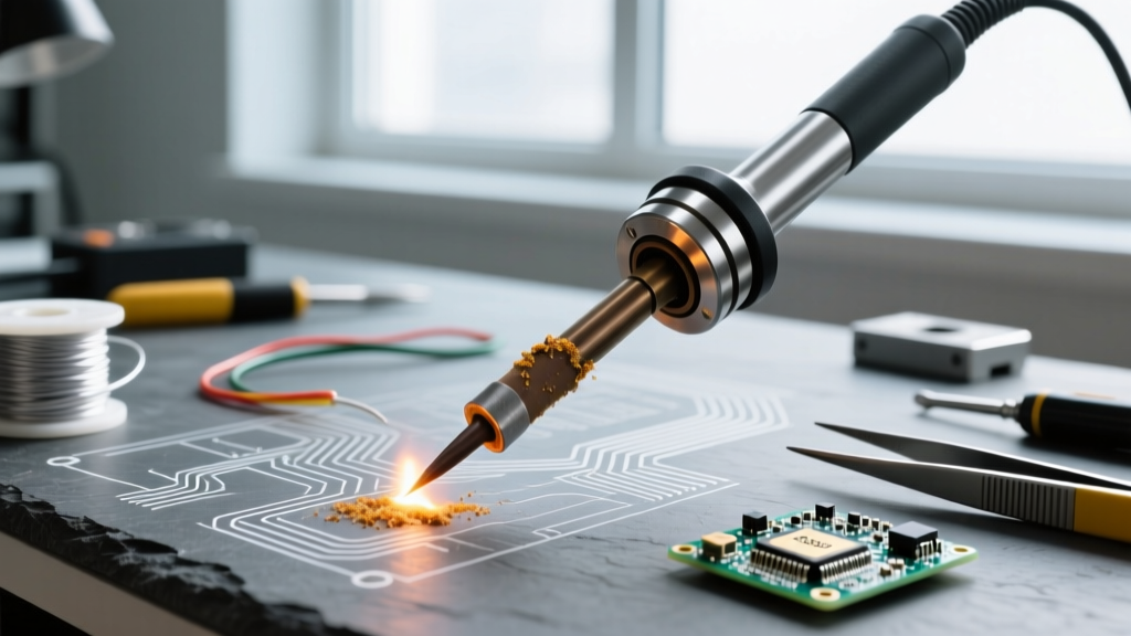
- Tip Oxidation: Iron-plated copper tips degrade rapidly above 380°C. The flux carbonizes onto the tip, forming a black, insulating crust that ruins thermal transfer, forcing the operator to turn the heat up even further—a vicious cycle that destroys $15 tips in a matter of days.
- Pad Lifting: The Tg (glass transition temperature) of standard FR-4 is around 135°C to 140°C. Prolonged localized heating causes the epoxy resin to soften and expand at a different rate than the copper, shearing the barrel of the plated through-hole (PTH) or lifting surface mount pads entirely off the substrate.
Advanced Thermal Management for High-Mass Components
When soldering heavy components like TO-220 power transistors, large RF shielding cans, or multi-layer ground plane vias, the standard advice of "turn up the heat" is incorrect. Cranking your station to 420°C will cook the surrounding SMDs and damage the board. Instead, use the following professional methodologies:
1. Maximize Tip Contact Area (Thermal Coupling)
Heat transfer is governed by Fourier's Law, where the rate of heat transfer is directly proportional to the contact area. Never use a fine conical tip (like a Hakko T18-I) for heavy joints. Switch to a wide chisel (e.g., T18-D32) or a large bevel tip (T18-C4). A massive tip holds more thermal energy (Joules) and transfers it into the lead and pad simultaneously, allowing you to keep the station at a safe 340°C while achieving a 2-second wetting time.
2. Implement Bottom Preheating
For 6-layer PCBs or boards with extensive internal copper pours, a soldering iron alone cannot overcome the thermal dissipation. Use an IR or quartz bottom preheater (such as the Quick 853A, approx. $85) to elevate the entire PCB ambient temperature to 120°C - 140°C. This reduces the thermal delta (ΔT) between the iron and the joint. With the board preheated, a 340°C iron will flow SAC305 solder on a massive ground plane as easily as it would on a simple single-layer hobby board.
3. Utilize High-Thermal-Conductivity Flux
Liquid or tacky flux acts as a thermal bridge between the iron tip and the dry metal surfaces. Applying a generous amount of high-quality, mildly activated rosin flux (like Amtech NC-559-V2-TF) before applying the iron ensures immediate heat transfer, drastically reducing the required dwell time and protecting the component from prolonged thermal exposure.
Summary: The 2026 Best Practices
Mastering the ideal soldering iron temperature for electronics requires abandoning the "set it and forget it" mentality. Start with a baseline of 320°C for leaded and 350°C for lead-free assemblies. Rely on tip geometry and flux chemistry to manage high thermal mass, rather than brute-force heat. By respecting the thermodynamics of the IMC layer and leveraging modern PID-controlled hardware, you will produce joints that are not only visually pristine but mechanically and electrically robust for decades of service.