
The Unique Challenge of Headphone Wiring
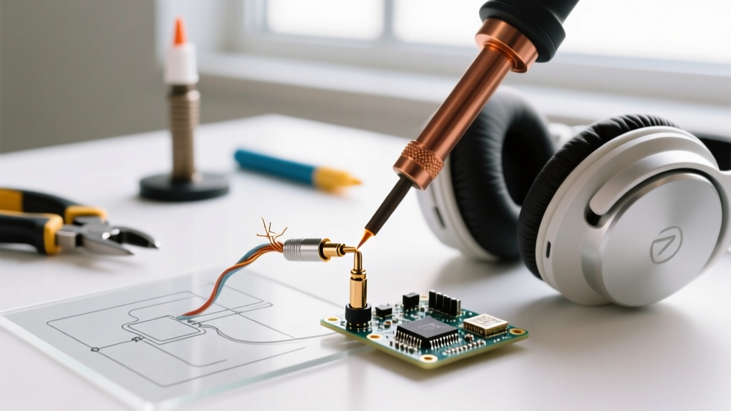
Repairing high-fidelity audio gear is a rite of passage for electronics enthusiasts, but applying a soldering iron on headphones presents a unique set of micro-soldering challenges. Unlike standard 22 AWG hookup wire found in breadboards or PCB through-holes, headphone cables are engineered for extreme flexibility and minimal weight. This results in the use of ultra-fine enameled copper wire (often 28 to 32 AWG) or multi-strand Litz wire. When troubleshooting a dead earcup or a faulty inline microphone, the physical fragility of these conductors means that standard soldering techniques will often lead to melted insulation, snapped cores, or high-resistance cold joints.
Why Standard Soldering Fails on Audio Cables
The primary obstacle when repairing headphone wires is the insulating enamel coating. This micro-thin layer of polyurethane or polyesterimide prevents short circuits between the left, right, and ground channels within the same cable jacket. If you attempt to solder this wire as-is, the enamel acts as a thermal and electrical barrier, resulting in a classic 'cold joint' where the solder balls up and refuses to wet the copper. Conversely, if you attempt to mechanically scrape the enamel off with a hobby knife, you will almost certainly nick the 32 AWG copper core, creating a mechanical weak point that will snap under the slightest tensile strain.
Essential Tools for Headphone Maintenance in 2026
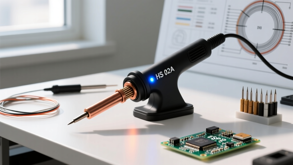
To successfully execute micro-soldering on audio cables, your thermal management must be precise. A high-wattage iron with slow thermal recovery will require you to hold the tip on the wire for too long, melting the surrounding TPE or PVC cable jacket. Modern smart soldering stations utilizing RISC-V microcontrollers or advanced ceramic heaters are ideal for this task.
| Soldering Station | Tip Type | Optimal Temp (Leaded) | Price Range (2026) | Best For |
|---|---|---|---|---|
| Pinecil V2 | TS100 / Pine64 Mini Tips | 330°C - 350°C | $26 - $32 | Portable repairs, budget-friendly precision |
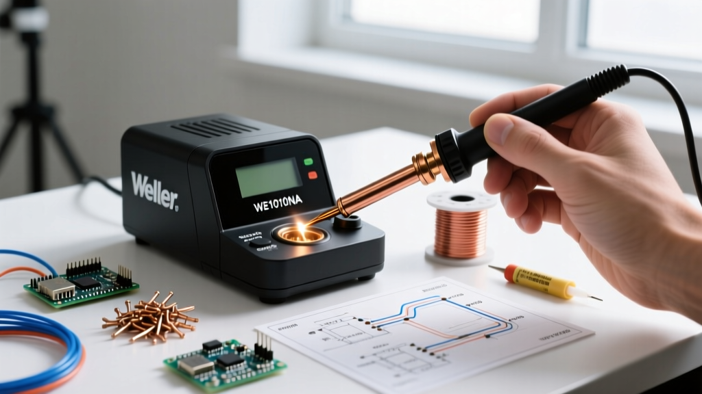
| Weller WE1010 | ETA (Chisel/Micro) | 340°C | $110 - $125 | Benchtop reliability, standard DIY |
| Hakko FX-951 | T12 Series (Micro-conical) | 345°C | $340 - $370 | Professional daily audio repair |
Equally important is your solder and flux selection. For headphone repair, always use 63/37 SnPb (Tin/Lead) eutectic solder in a 0.3mm or 0.5mm diameter. Eutectic solder transitions instantly from liquid to solid at 183°C without a 'plastic' (semi-solid) phase, drastically reducing the risk of disturbing the joint while it cools. Pair this with a high-quality rosin-based tack flux, such as Amtech NC-559-V2-TF or Chip Quik SMD291AX10.
Diagnosing the Fault: TRRS Pinouts and Multimeter Testing
Before applying heat, you must isolate the failure. Headphone cables typically fail at two stress points: the 3.5mm TRRS (Tip-Ring-Ring-Sleeve) plug, or the yoke where the cable enters the earcup. Set your digital multimeter to continuity mode (with the audible beep).
- CTIA Standard (Modern Apple/Android): Tip = Left Audio, Ring 1 = Right Audio, Ring 2 = Ground, Sleeve = Microphone.
- OMTP Standard (Legacy): Tip = Left Audio, Ring 1 = Right Audio, Ring 2 = Microphone, Sleeve = Ground.
Probe the plug contacts against the exposed wire at the earcup driver. If you find an open circuit on the Left Audio channel, you know exactly which enameled wire needs to be re-tinned and re-soldered to the driver pad.
Execution: Applying the Soldering Iron on Headphones
The most reliable method for stripping and tinning enameled headphone wire simultaneously is the 'Burn-and-Tin' technique. This leverages the heat of the iron and the chemical properties of the flux to vaporize the polyurethane coating without mechanical abrasion.
Expert Insight: Never use a soldering iron tip that has been 'dry burned' (oxidized black). An oxidized tip will not transfer heat efficiently to the micro-wire, forcing you to hold the iron in place for 10+ seconds, which will inevitably melt the internal Kevlar or nylon tensile strands woven into the headphone cable. Always re-tin your tip immediately before touching the audio wire.
- Prep the Cable: Carefully strip back 15mm of the outer PVC/TPE jacket using precision wire strippers or a thermal wire stripper. Separate the individual enameled strands. You will often see bare copper or Kevlar threads mixed in; these are for tensile strength and do not carry audio. Trim them away flush.
- Load the Tip: Set your station to 340°C (644°F). Apply a generous bead of 0.5mm 63/37 solder to a clean, fluxed tip, creating a molten 'blob' of solder.
- Apply Flux: Dip the separated enameled headphone wires into your rosin flux pot, or paint the flux onto the wire using a fine brush. Flux is non-negotiable here; it prevents oxidation and aids in thermal transfer.
- The Burn-and-Tin: Submerge the fluxed wire directly into the molten solder blob on your iron tip. Hold it there for 2 to 4 seconds. You will see a tiny wisp of smoke as the polyurethane enamel melts and vaporizes. The flux will pull the molten solder up into the bare copper via capillary action.
- Wick and Inspect: Pull the wire away. It should now be fully silver-coated (tinned) with no black enamel residue. If black spots remain, apply more flux and repeat for 1 second. Do not scrape.
For deeper industry standards on micro-soldering and wetting protocols, the NASA Workmanship Standards provide exhaustive visual criteria for acceptable solder joints on fine-gauge wire, emphasizing the necessity of complete wetting and smooth fillets without disturbed grain structures.
Troubleshooting Common Soldering Defects
Even with the right technique, micro-soldering is prone to specific failure modes. Here is how to troubleshoot the most common issues when working on audio gear:
1. High-Resistance 'False' Continuity
Symptom: The multimeter beeps, but the audio is incredibly quiet or distorted, lacking bass response.
Cause: Only one or two strands of a multi-strand Litz wire actually made contact with the solder pad, or a thin layer of unburned enamel is acting as a resistor.
Fix: Desolder the joint using 1.0mm copper desoldering braid (wicking). Re-flux heavily, increase iron temperature by 10°C to ensure complete enamel breakdown, and re-tin.
2. Melted Driver Pads
Symptom: The copper trace lifts off the plastic diaphragm of the headphone driver.
Cause: Holding the iron on the ultra-thin driver pad for too long. Driver pads are often glued to PET film with heat-sensitive adhesives.
Fix: Pre-tin both the wire and the driver pad separately. Use a pair of precision titanium tweezers as a heat sink clamped to the wire just above the joint to draw thermal energy away from the driver diaphragm during the final mating process.
3. Solder Wicking Under the Insulation
Symptom: The wire becomes stiff and brittle up to 10mm inside the outer jacket.
Cause: Capillary action pulled liquid solder up under the wire's primary insulation, creating a rigid point that will snap under flexing.
Fix: Keep the tinned section as short as possible (under 3mm). Use a lower wattage setting or a micro-conical tip to restrict the thermal footprint. For comprehensive guides on managing capillary action and flux dynamics, SparkFun's SMD and fine-wire soldering tutorials offer excellent visual breakdowns of solder flow mechanics.
Post-Solder Maintenance and Strain Relief
A perfect solder joint on a 32 AWG headphone wire is mechanically worthless if it lacks strain relief. The moment the user yanks the cable, the tensile force will transfer directly to the brittle solder fillet, tearing it from the PCB or driver pad.
After verifying continuity and audio channel separation, you must immobilize the joint. The professional standard is to apply a drop of UV-curable solder mask resin or a flexible cyanoacrylate (CA) glue over the solder pad and the first 2mm of the wire's insulation. Cure it under a 3W UV flashlight for 60 seconds. This creates a flexible, shock-absorbing boot that transfers mechanical stress away from the electrical joint. Finally, slide a piece of 2mm adhesive-lined (dual-wall) heat shrink tubing over the repair area and apply heat until the inner meltable adhesive oozes out the ends, sealing the repair against moisture and physical strain.
Maintaining Your Iron for Future Audio Repairs
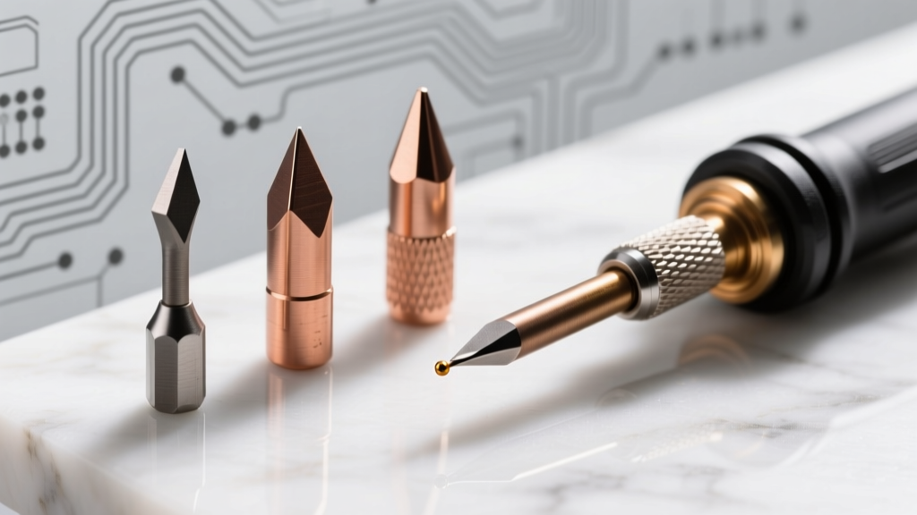
Using a soldering iron on headphones requires a pristine tip. Enameled wire residue and burned rosin flux will quickly pit and degrade micro-conical tips. After every repair session, clean the tip using dry brass wool (never a wet sponge, which causes thermal shock and micro-cracking in the iron plating). Apply a thick coat of 63/37 solder to the tip before powering down the station. This 'sacrificial tinning' layer will oxidize instead of the iron's factory iron-plating, ensuring your station is ready for the next micro-soldering challenge.