
The Anatomy of Soldering Iron Metal: Beyond the Surface
When electronics engineers and hobbyists discuss soldering iron metal, they are rarely referring to a single elemental material. Modern soldering tips and stations are complex metallurgical assemblies engineered to solve a fundamental physics problem: how to transfer massive amounts of thermal energy into a localized joint without the tool itself dissolving, oxidizing, or degrading. In 2026, as high-density interconnect (HDI) PCBs and miniaturized 01005 surface-mount components dominate the market, understanding the exact metallurgical stack of your soldering iron is no longer optional—it is a prerequisite for process reliability.
This deep dive explores the specific metals, alloys, and plating layers that constitute modern soldering irons, analyzing their thermal conductivity, failure modes, and maintenance requirements.
The Copper Core: Oxygen-Free High Conductivity (OFHC)
The heart of almost every high-quality soldering iron tip is a copper core. However, manufacturers do not use standard commercial copper. They utilize Oxygen-Free High Thermal Conductivity (OFHC) copper, typically C10100 or C10200 grade. Standard copper contains trace amounts of oxygen and other impurities that create microscopic voids and grain boundaries, which scatter phonons and impede heat flow.
OFHC copper boasts a thermal conductivity of approximately 398 W/m·K at room temperature. While this drops slightly as temperatures approach 400°C, it remains vastly superior to almost all other affordable metals. The core is precision-machined via CNC or cold-forging into specific geometries—chisel, bevel, hoof, or conical—dictating the thermal mass and contact surface area of the tip.
Why Not Silver or Diamond?
While silver has a higher thermal conductivity (~429 W/m·K) and synthetic diamond composites can exceed 1000 W/m·K, the cost-to-performance ratio makes them unviable for replaceable tips. Furthermore, silver is highly susceptible to leaching (dissolving into molten tin-based solders), meaning a pure silver tip would be destroyed in a matter of hours. Copper provides the optimal balance of rapid heat transfer and structural integrity, provided it is properly shielded.
The Iron Plating Layer: The Sacrificial Shield
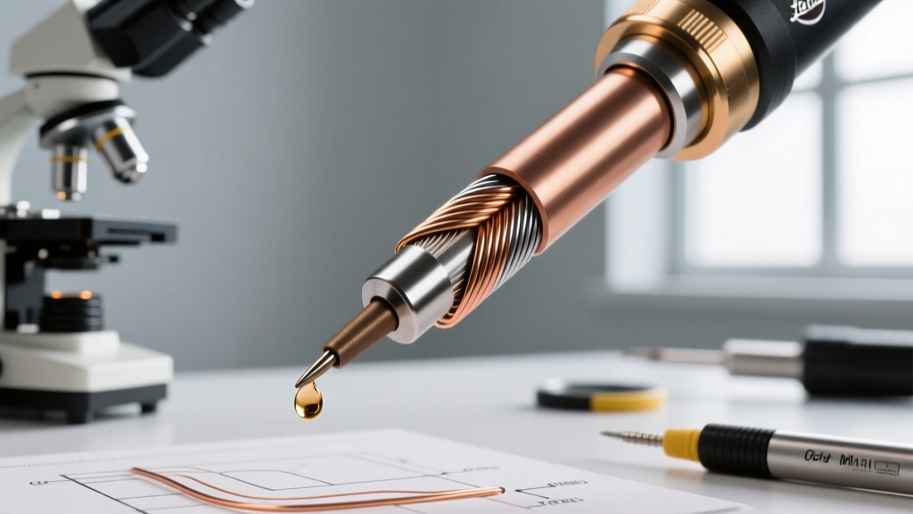
Because molten solder aggressively dissolves bare copper, the copper core must be encased in a protective metal. This is where electroplated iron comes into play. The working surface of a modern soldering iron tip is coated with a layer of pure iron, typically ranging from 0.10mm to 0.15mm in thickness.
Iron is chosen because it is highly resistant to dissolution by molten tin-silver-copper (SAC) alloys compared to copper or silver. However, iron has a significantly lower thermal conductivity (~80 W/m·K). This creates an engineering bottleneck: if the iron layer is too thick, thermal transfer is choked, leading to cold joints and prolonged dwell times. If the iron layer is too thin, the tip will suffer from rapid leaching and premature failure. Premium manufacturers like Hakko and JBC tightly control this electroplating process to maintain the exact tolerance required for rapid thermal recovery.
The Chromium/Nickel Barrier Layer
Beneath the iron plating and above the copper core, a microscopic barrier layer of chromium or nickel is often applied. This layer serves a critical secondary function: it prevents molten solder from wicking up the sides of the tip and creeping onto the heating element or barrel. Without this non-wetting barrier, solder would quickly bridge the gap between the tip and the station's ceramic heater, causing catastrophic electrical shorts and thermal sensor failures.
Metallurgical Stack Comparison
| Layer / Component | Primary Metal / Alloy | Thickness / Volume | Thermal Conductivity (W/m·K) | Primary Function |
|---|---|---|---|---|
| Inner Core | OFHC Copper (C10100) | Bulk (85-90% of tip mass) | ~398 | Rapid thermal transfer from heater to joint |
| Barrier Layer | Chromium or Nickel | ~0.01mm | ~90 (Cr) / ~90 (Ni) | Prevents solder wicking up the barrel |
| Working Surface | Electroplated Pure Iron | 0.10mm - 0.15mm | ~80 | Protects copper from molten solder leaching |
| Heating Element Wire | Nichrome 80/20 (Ni-Cr) | Variable (Wire gauge) | ~11 | Resistive heat generation (Legacy/Standard) |
| Modern Heater Core | Thick-Film Ceramic / Alumina | Integrated Cartridge | ~30 (Alumina) | Instant thermal recovery, integrated thermocouple |
Heating Element Metallurgy: Nichrome vs. Ceramic Cartridges
The metals used to generate heat have evolved drastically over the last decade. Traditional soldering stations rely on Nichrome (Nickel-Chromium 80/20 alloy) wire wound around a mica or ceramic insulator. Nichrome is prized for its high electrical resistance and its ability to form a protective layer of chromium oxide when heated, which prevents the wire from burning out at high temperatures. However, Nichrome heaters suffer from high thermal mass and slow response times.
In 2026, the industry standard for professional work has shifted to thick-film ceramic heaters and integrated cartridge systems (such as JBC's C245/C115 or Weller's RT series). In these systems, a resistive metal trace is printed directly onto an alumina (aluminum oxide) ceramic substrate. The thermocouple is embedded directly inside the cartridge, mere millimeters from the tip's working face. This eliminates the air gap found in older sleeve-style tips, reducing thermal resistance and allowing the station's PID controller to deliver bursts of current to recover heat in under two seconds.
Failure Modes: How Soldering Iron Metal Degrades
Understanding the metallurgy of your iron is only half the battle; recognizing how these metals fail under thermal stress is crucial for maintaining IPC-compliant solder joints. According to the IPC J-STD-001 standard, maintaining proper thermal profiles is critical to avoiding intermetallic compound (IMC) fracturing, which is directly tied to tip degradation.
1. Iron Leaching (Dissolution)
The transition to lead-free solders, specifically SAC305 (Sn96.5/Ag3.0/Cu0.5), has been brutal on soldering iron metal. Lead-free alloys require higher processing temperatures (340°C to 380°C) and possess a higher tin content. Molten tin acts as a solvent for iron. At 380°C, the leaching rate of the iron plating can be three to four times faster than with legacy Sn63/Pb37 eutectic solder. Once the iron layer is breached, the molten solder reaches the copper core, rapidly hollowing out the tip and rendering it useless.
2. Oxidation and Thermal Insulation
When the iron-plated surface is exposed to atmospheric oxygen at elevated temperatures, it forms Iron(III) oxide (Fe2O3). Unlike the metallic iron beneath it, iron oxide is a severe thermal insulator. A heavily oxidized tip will read 380°C on the station's display, but the actual thermal energy transferred to the solder joint may be insufficient to melt the flux core, leading to the dreaded "cold joint." As detailed in Hakko's official tip care guidelines, oxidation accelerates exponentially above 400°C, making idle temperature management critical.
3. Intermetallic Compound (IMC) Overgrowth
If the iron layer is compromised and copper is exposed, the copper reacts with tin to form Cu6Sn5 and Cu3Sn intermetallic compounds. While a thin IMC layer is necessary for a metallurgical bond, excessive IMC growth due to a degraded tip creates a brittle, glass-like joint that will fracture under mechanical or thermal shock, a major failure point in automotive and aerospace electronics.
Expert Insight: Never file or sand a modern iron-plated tip. Abrasives will instantly remove the 0.1mm iron layer, exposing the copper core to immediate destruction. If a tip is heavily oxidized, use a chemical tip tinner containing tin powder, aggressive flux, and trace silver to chemically reduce the oxide and re-tin the surface.
2026 Maintenance Protocols for Prolonging Tip Life
To maximize the lifespan of your soldering iron metal stack, implement the following operational protocols, especially when working with aggressive lead-free or halogen-free fluxes:
- Utilize Sleep Modes: Modern stations like the Pace ADS200 or JBC DDE feature auto-sleep. Dropping the tip temperature to 150°C when idle reduces the oxidation rate of the iron plating by over 80% compared to idling at 350°C.
- Always Leave a Solder Blob: Before placing the iron back in its holder, melt a large bead of solder over the entire working face. This sacrificial layer acts as a physical barrier against atmospheric oxygen. The next time you pick up the iron, simply wipe the oxidized blob on a brass wire sponge, revealing a pristine, pre-tinned iron surface.
- Use Brass Wire Sponges, Not Wet Cellulose: Wet cellulose sponges cause rapid thermal shock. The sudden contraction and expansion of the metal can cause micro-fractures in the iron plating, allowing solder to seep through and attack the copper core. Brass wool absorbs the dross without dropping the tip temperature drastically.
- Match Tip Mass to the Joint: Using a micro-conical tip (low thermal mass) to solder a heavy ground plane will force the station to run at maximum voltage continuously, overheating the internal ceramic heater and accelerating tip degradation. Always use the largest chisel or bevel tip that the pad geometry allows, as recommended by NASA's Electronic Parts and Packaging (NEPP) soldering guidelines.
Conclusion
The phrase "soldering iron metal" encompasses a highly engineered stack of OFHC copper, electroplated iron, chromium barriers, and advanced ceramic heaters. By understanding the specific thermal properties and failure modes of these metals, technicians can optimize their thermal profiles, reduce consumable costs, and ensure that every solder joint meets the rigorous demands of modern electronics manufacturing.