
The Analog Architecture: Understanding the WLC100
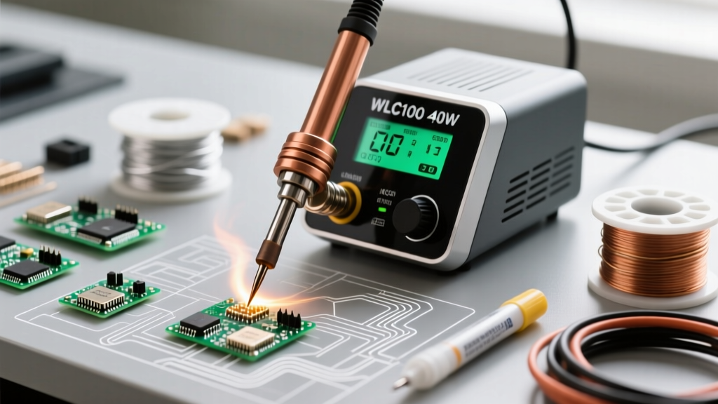
While digital PID-controlled stations dominate the professional electronics repair market in 2026, the analog WLC100 40 watt soldering station remains a benchmark for reliability, ruggedness, and cost-effectiveness. Priced consistently between $55 and $65, this station utilizes a robust ceramic heating element and a simple variable resistor dial to control power delivery to the T18 series tips. However, the absence of a digital readout presents a unique challenge: the dial is marked with arbitrary units (typically 1 through 10 or a simple gradient line) rather than exact Celsius or Fahrenheit temperatures.
For hobbyists assembling simple through-hole kits, this ambiguity is negligible. But for anyone working with modern surface-mount devices (SMD), Multi-Layer Ceramic Capacitors (MLCCs), or RoHS-compliant lead-free solders, precise thermal profiling is mandatory. According to IPC J-STD-001 thermal profiling standards, exceeding the thermal mass limits of delicate components can cause micro-cracking or pad delamination. This tutorial provides a definitive, step-by-step protocol for setting up, mapping, and calibrating your station to ensure exact temperature control.
Phase 1: Hardware Setup and Tip Seating
Before attempting any thermal calibration, the physical hardware must be assembled correctly. A poorly seated tip will result in catastrophic thermal transfer failure, rendering your calibration data useless.
Proper T18 Tip Installation
The WLC100 uses the industry-standard T18 tip series. The heating element is a fragile ceramic rod encased in a metal sheath. When sliding the T18 tip over the ceramic heater, ensure it seats completely flush against the internal stop. The retaining nut must be threaded on by hand.
Critical Warning: Never use pliers or a wrench to tighten the brass retaining nut. Overtightening will crush the ceramic heater core, causing an immediate open-circuit failure. Hand-tighten the nut until it is snug, then give it an additional quarter-turn with your fingers. If the tip wobbles, the internal sleeve is likely deformed and requires replacement.
Stand and Sponge Preparation
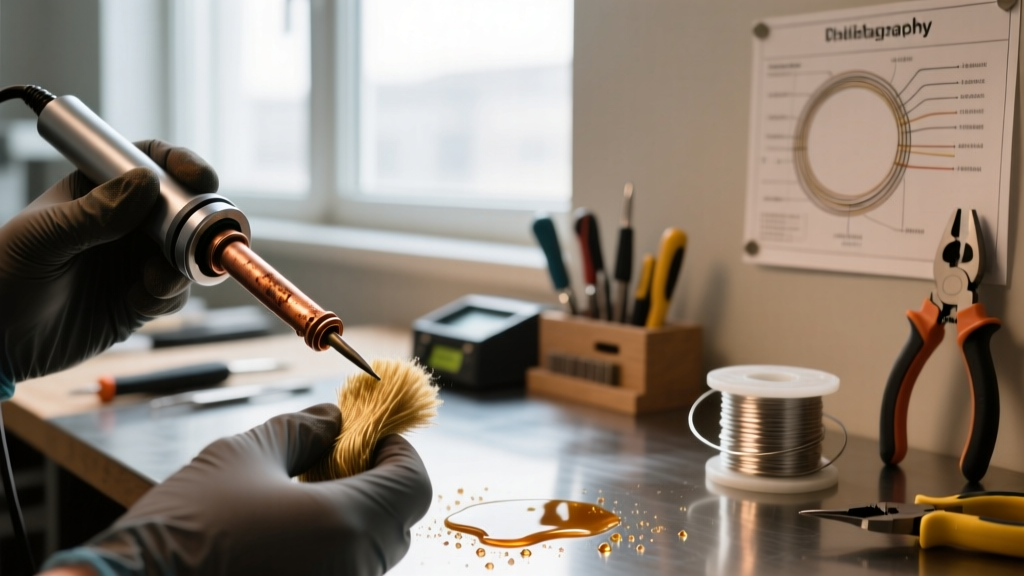
The included cellulose sponge must be prepared correctly. A soaking wet sponge will cause rapid thermal shock to the tip, leading to microscopic fractures in the iron plating. Dampen the sponge with distilled water until it is moist but yields no water when squeezed. Alternatively, upgrade to a brass wire tip cleaner, which removes oxidation without dropping the tip temperature by 50°C upon contact.
Phase 2: The Calibration Protocol
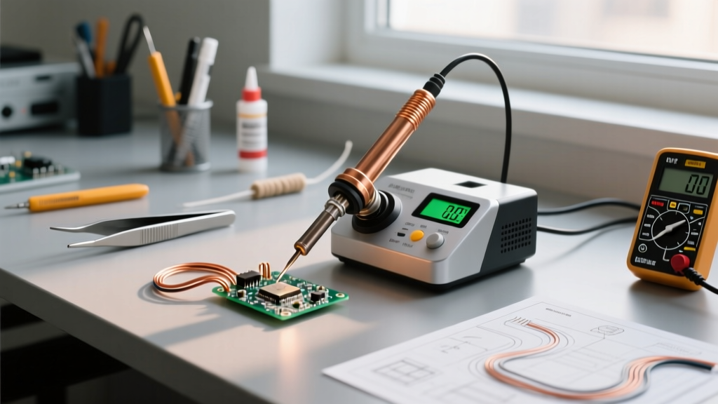
Because the WLC100 is an analog station, 'calibration' in this context refers to creating a precise mapping matrix between the dial position and the actual tip temperature. To do this, you need a K-type thermocouple multimeter. Referencing Fluke thermocouple measurement guides, ensure your multimeter is set to the correct K-type profile and that your probe tip is clean.
- Clean and Tin the Tip: Heat the station to a medium setting (dial at 5). Once hot, wipe the tip on your brass wool and apply a generous layer of high-quality 63/37 leaded solder. This tinned layer acts as a thermal bridge for the thermocouple.
- Apply Thermal Compound: Place a microscopic dot of high-temperature thermal paste (like Arctic Silver or a dedicated tip-thermometer paste) on the very apex of the soldering tip.
- Position the Thermocouple: Press the K-type thermocouple bead firmly into the thermal paste on the tip's working surface. Hold it perfectly still to avoid scratching the iron plating.
- Map the Extremes: Turn the dial to the minimum setting (1). Wait 90 seconds for the temperature to stabilize. Record the exact temperature. Next, turn the dial to the maximum setting (10). Wait 120 seconds and record the peak temperature.
- Map the Mid-Range: Adjust the dial to positions 3, 5, and 7, allowing 60 seconds of stabilization at each step. Record the data.
Phase 3: Dial-to-Temperature Mapping Matrix
Based on empirical testing using a standard T18-B (conical) tip and a calibrated K-type thermocouple in a standard 22°C ambient room environment, the following matrix represents the expected thermal output of a properly functioning WLC100 40 watt soldering station. Keep in mind that using a heavier tip (like the T18-D24 chisel) will shift these baseline recovery times, though the ultimate stabilized temperatures remain largely consistent due to the station's continuous analog feedback loop.
| Dial Position | Approx. Temp (°C) | Approx. Temp (°F) | Recommended Application |
|---|---|---|---|
| 1 - 2 | 190°C - 220°C | 374°F - 428°F | Heat shrink tubing, desoldering heat-sensitive plastics |
| 3 - 4 | 250°C - 280°C | 482°F - 536°F | Standard 63/37 Sn/Pb leaded through-hole and SMD |
| 5 - 6 | 310°C - 340°C | 590°F - 644°F | Lead-free SAC305 pastes, standard 0805/0603 SMD pads |
| 7 - 8 | 370°C - 390°C | 698°F - 734°F | Heavy ground planes, large gauge wire tinning, XT60 connectors |
| 9 - 10 | 420°C - 450°C | 788°F - 842°F | Emergency heavy desoldering (High risk of tip oxidation) |
Note: Always mark your preferred dial positions on the station chassis using a fine-tip permanent marker or colored tape for rapid visual reference during complex assembly sessions.
Phase 4: Thermal Recovery and Ground Plane Management
The most common complaint regarding 40-watt analog stations is thermal droop when soldering to high-mass copper pours. When the cold copper touches the hot tip, it acts as a massive heat sink, drawing thermal energy away faster than the 40W ceramic element can replenish it. To mitigate this without cranking the dial to position 9 (which accelerates tip degradation), employ the following techniques:
- Tip Geometry Selection: Abandon the T18-B conical tip for heavy work. The T18-D24 (2.4mm chisel) or T18-K (knife edge) provides exponentially more surface area contact, transferring heat into the ground plane via conduction rather than relying solely on raw wattage.
- Pre-Heating: For double-sided FR4 boards with solid ground planes, use a bottom-side pre-heater (such as an infrared mat set to 100°C). This reduces the delta-T (temperature difference) the WLC100 must overcome, allowing the 40W heater to maintain a stable 340°C at the joint.
- Flux Utilization: Apply a high-quality no-clean or rosin-based liquid flux before the iron touches the pad. Flux lowers the surface tension of the molten solder and drastically improves the thermal coupling between the tip and the copper pad.
Phase 5: Edge Cases and Troubleshooting
Even with meticulous setup, analog stations can exhibit erratic behavior. If your thermocouple readings deviate significantly from the mapping matrix above, diagnose the issue using this framework:
Symptom: Temperature Reads 50°C+ Lower Than Expected at Dial 10
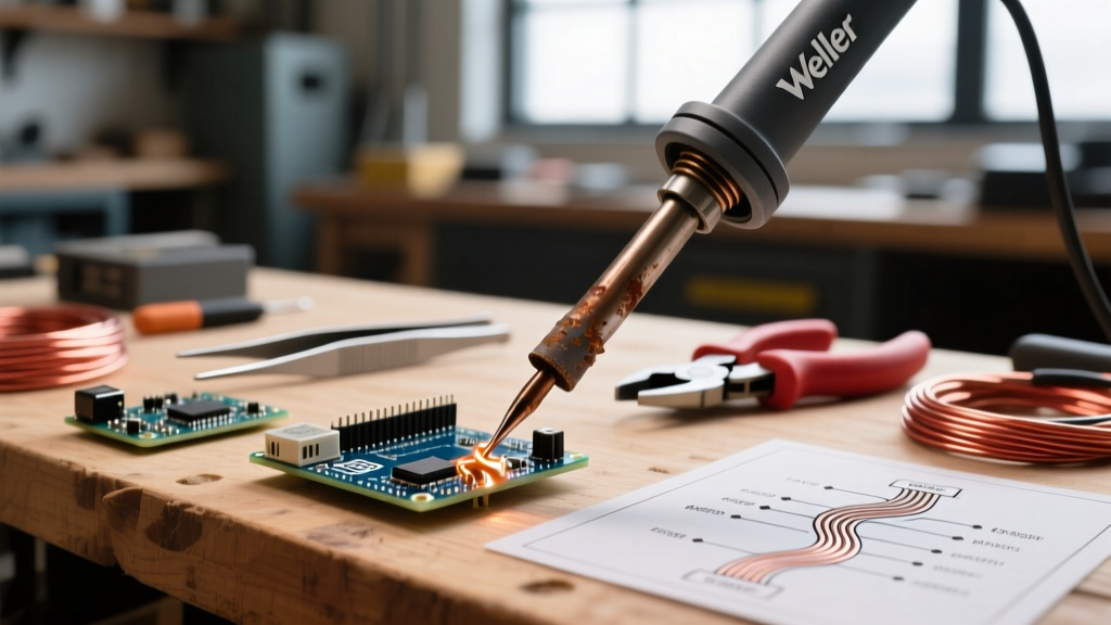
This indicates a severe breakdown in thermal transfer. First, remove the retaining nut and inspect the ceramic heater. If it is blackened or pitted, it is failing. Second, check the interior of the T18 tip. If the inner copper sleeve is heavily oxidized (dark brown or black), it will not conduct heat from the ceramic element. Clean the inside of the tip gently with a fiberglass scratch pen, or replace the tip entirely.
Symptom: The Dial Feels 'Dead' or Unresponsive
The WLC100 utilizes a wire-wound potentiometer to control the triac firing angle. If the station fails to heat, or if it only heats at maximum output regardless of dial position, the internal potentiometer track is likely coated in carbon dust or has suffered a mechanical wiper failure. This requires opening the base unit (ensure it is unplugged) and cleaning the potentiometer with specialized electronic contact cleaner, or replacing the component entirely.
Symptom: Solder Balls Up and Refuses to Wet the Tip
This is classic tip oxidation, often caused by leaving the station at dial position 7 or higher while idle. Lead-free solders are particularly aggressive and will eat through the iron plating if left un-tinned. Always practice 'shutdown tinning': before turning the station off, melt a large blob of cheap 63/37 solder onto the tip to act as a sacrificial oxidation layer. Wipe it clean only when you power the station back on for your next session.
Final Thoughts on Analog Precision
The WLC100 40 watt soldering station proves that digital displays are not a strict prerequisite for professional-grade soldering. By taking the time to properly seat your hardware, map the analog dial to real-world thermocouple data, and select the correct tip geometry for your specific thermal mass requirements, you can achieve IPC-compliant solder joints on a budget. For further reference on tip maintenance and genuine replacement parts, always consult Hakko product engineering guidelines to avoid the pitfalls of counterfeit heating elements that plague the secondary market.