
Soldering Iron How Hot: The Thermal Delta Explained
When electronics hobbyists and assembly technicians ask, "soldering iron how hot should it be," the answer is never a single static number. While a standard 40W to 60W soldering iron can physically reach maximum temperatures exceeding 480°C (896°F), operating at these extremes will rapidly destroy both your printed circuit boards (PCBs) and your soldering tips. As of 2026, the industry standard focuses on the thermal delta—the precise temperature difference between the solder alloy's melting point and the required tip temperature to maintain a stable liquidus state during heat transfer.
Melting Points vs. Optimal Tip Temperatures
A common misconception is setting the iron dial exactly to the solder's melting point. In reality, the moment the cold copper pad and component lead touch the tip, the localized temperature plummets. To achieve a proper metallurgical bond within 2 to 3 seconds, your tip must be significantly hotter than the alloy's liquidus threshold. According to guidelines from IPC and modern workmanship standards, you must account for thermal mass and heat dissipation.
| Solder Alloy | Composition | Melting Point (Liquidus) | Optimal Tip Temperature | Primary Application |
|---|---|---|---|---|
| Sn63/Pb37 | 63% Tin, 37% Lead (Eutectic) | 183°C (361°F) | 315°C - 340°C (600°F - 645°F) | General DIY, prototyping, aerospace |
| SAC305 | 96.5% Sn, 3% Ag, 0.5% Cu | 217°C (423°F) | 350°C - 380°C (662°F - 716°F) | Commercial RoHS-compliant electronics |
| Sn96.5/Ag3/Cu0.5 | Lead-Free Eutectic | 217°C (423°F) | 350°C - 380°C (662°F - 716°F) | High-reliability lead-free assemblies |
| Sn5/Pb93.5 | High-Temp Lead | 308°C (586°F) | 400°C+ (752°F+) | Die-attach, multi-step reflow |
| 95/5 Tin/Antimony | Plumbing Grade | 227°C (441°F) | 380°C - 420°C (716°F - 788°F) | Copper pipes, stained glass |
The Physics of Thermal Recovery and Tip Mass
Understanding how hot your soldering iron gets is only half the equation; the other half is how fast it recovers that heat. A cheap $20 60W iron with a massive, poorly calibrated ceramic heating element might read 400°C on its dial, but when applied to a heavy ground plane, the tip temperature will crash to 200°C and stay there, resulting in a grainy, disturbed cold joint.
Modern stations utilize advanced closed-loop feedback. For example, the Hakko FX-888D uses a thermocouple embedded near the tip to constantly adjust power via a PID controller. Meanwhile, high-end systems like the Metcal MX-5200 use Curie-point technology. The tip itself is made of a ferromagnetic alloy that loses its magnetic permeability at a specific temperature (e.g., 390°C for a 700-series tip), physically cutting off the induction heating until it cools, ensuring absolute thermal stability without digital sensors.
Expert Insight: When soldering massive thermal sinks like XT90 connectors or thick copper pour planes, do not simply turn up the temperature to 450°C. Instead, increase the thermal mass by switching to a chisel or bevel tip (like the Hakko T18-D24 or Weller ET series). A larger tip surface area transfers joules of heat much faster than a micro-pencil tip at a higher temperature.
The Role of Flux Chemistry in Temperature Selection
Temperature does not exist in a vacuum; it interacts directly with your flux chemistry. In 2026, the market is dominated by no-clean and water-soluble fluxes, each with distinct thermal activation curves. No-clean rosin-based fluxes (like those found in Kester 44 or MG Chemicals 4900) typically begin activating at 150°C and reach peak cleaning efficacy around 220°C. If your iron is set too low (e.g., 280°C), the heat transfer is too slow, and the flux may exhaust its cleaning power before the solder fully wets the pad, resulting in a weak, high-resistance joint.
Conversely, water-soluble (OA) fluxes are highly aggressive and designed for rapid activation. They tolerate higher tip temperatures (up to 380°C) but will leave a highly corrosive residue if not cleaned with distilled water or specialized saponifiers immediately after cooling. Understanding your flux's Material Safety Data Sheet (MSDS) and Technical Data Sheet (TDS) is just as critical as knowing your alloy's melting point.
Real-World Failure Modes: When Your Iron is Too Hot
Pushing your iron past 380°C (716°F) for standard electronics work triggers a cascade of chemical and physical failures:
- Flux Flash-Off: Rosin-based fluxes (RMA) activate around 150°C to 220°C to strip oxidation. If your tip is 420°C, the flux vaporizes instantly upon contact, leaving the molten solder exposed to oxygen. The result is a dry, oxidized ball that refuses to wet the pad.
- Substrate Delamination: Standard FR-4 fiberglass has a Glass Transition Temperature (Tg) between 130°C and 170°C. Prolonged exposure to a 400°C+ tip causes the epoxy resin to expand rapidly, lifting the copper trace right off the board.
- Tip Oxidation and Pitting: At temperatures above 400°C, the iron plating on the copper core oxidizes at an exponential rate. You will notice a black, crusty buildup that solder simply rolls off of, permanently ruining a $10-$15 replacement tip.
Portable vs. Benchtop: Thermal Performance in the Field
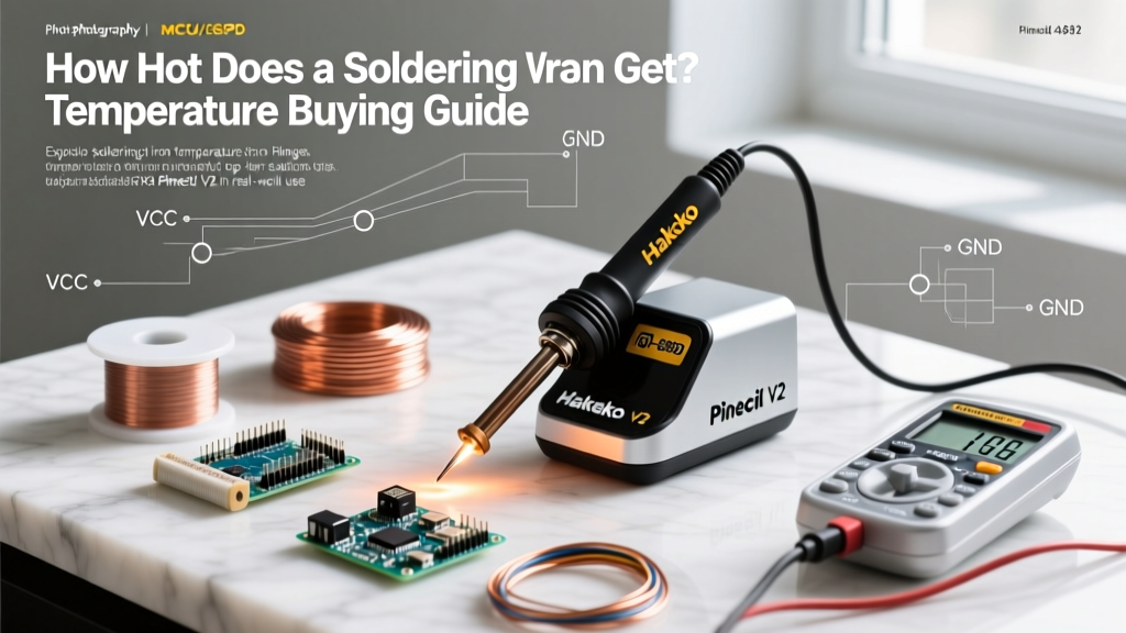
The rise of USB-C PD (Power Delivery) soldering irons has revolutionized field repairs, but it introduces new thermal dynamics. A benchtop station like the Weller WE1010NA (70W) draws continuous AC power, allowing its heating element to recover from thermal shock in under two seconds. In contrast, a portable iron like the Pine64 Pinecil V2 relies on a RISC-V chip managing a PID algorithm powered by a 65W to 245W USB-C GaN charger.
While the Pinecil V2 boasts an impressive heating rate (reaching 350°C in roughly 6 seconds), its physical tip mass is smaller than standard T18 or ET series tips. When tackling heavy ground planes, portable irons will experience a deeper thermal drop and require a slightly higher setpoint (e.g., bumping from 340°C to 360°C) to compensate for the lower overall joule-transfer capacity. For continuous heavy-duty production work, a 100W+ benchtop station remains the undisputed king of thermal stability.
Application-Specific Temperature Profiles
1. Fine-Pitch PCB Work (0402 to 0805 SMD Components)
For delicate surface-mount work, use a micro-pencil tip (e.g., 0.4mm) and set your station to 320°C (608°F) with Sn63/Pb37. The thermal mass of the components is so low that higher temperatures will melt the plastic housings of nearby ICs or lift micro-pads. Dwell time should be under 1.5 seconds per joint.
2. Heavy Ground Planes and XT60/XT90 Connectors
Set your iron to 360°C (680°F) and use a wide bevel tip. Apply a small amount of scrap solder to the tip to create a thermal bridge, press firmly against the wire and cup simultaneously, and feed 63/37 rosin-core wire. If using SAC305 lead-free, bump the station to 380°C (716°F), but be prepared for accelerated tip wear.
3. Copper Plumbing and Stained Glass
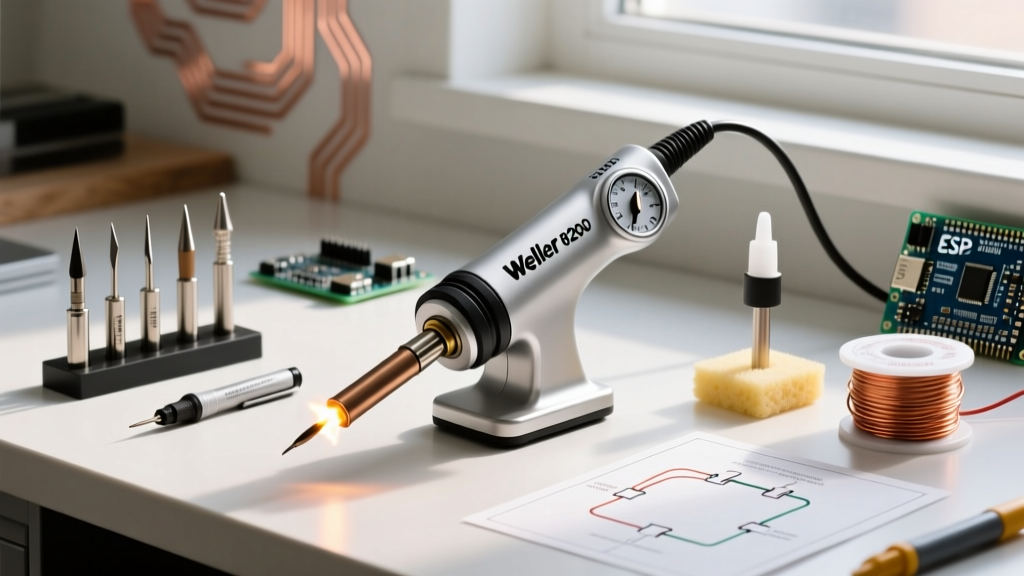
Electronics stations are entirely unsuited for plumbing. Soldering 1/2-inch or 3/4-inch copper pipes requires a high-wattage (100W+) iron or a propane torch. If using a heavy-duty electric iron like the Weller 8200PK cordless iron, expect tip temperatures to exceed 450°C (842°F) to overcome the massive heat-sinking effect of water-filled or thick-walled copper pipes. Always use 95/5 plumbing-grade solder and water-soluble paste flux.
Verifying Your Tip Temperature
Never blindly trust the digital readout on your soldering station. The display shows the setpoint or the temperature near the heating element, not the actual temperature at the very edge of the tip. To ensure compliance with professional standards, technicians use a tip thermometer like the Hakko FG-100B.
These devices use a specialized K-type thermocouple with a microscopic bead welded to the junction. By applying a dab of thermal paste or fresh solder to the sensor and pressing your tip against it, you can measure the true surface temperature within ±1°C. If your station reads 350°C but the FG-100B reads 320°C, you must use the station's calibration offset menu to correct the thermal drift—a critical step for any lab aiming for ISO 9001 or IPC-A-610 compliance. Manufacturers like Hakko and Weller provide detailed calibration matrices in their service manuals to assist with this precise tuning.
Final Takeaways
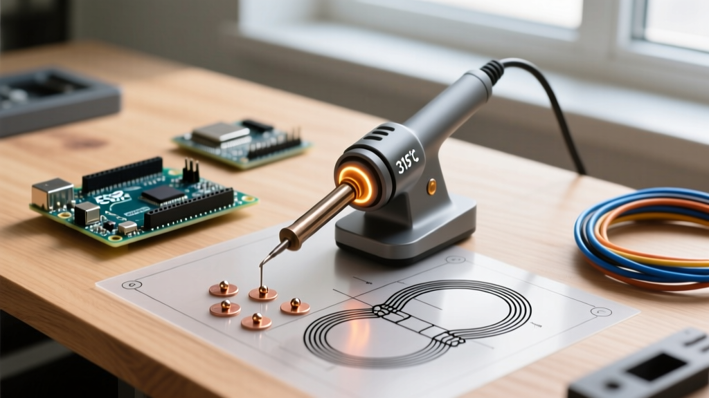
The question of "soldering iron how hot" is ultimately a question of thermal management. Match your tip geometry and temperature to the specific thermal mass of your joint. Keep leaded electronics work between 315°C and 340°C, respect the higher requirements of SAC305 lead-free alloys, and invest in a station with genuine thermal recovery rather than relying on raw, unregulated wattage. By understanding the physics of heat transfer, you will produce reliable, shiny, and structurally sound solder joints every time.