
The Anatomy of a Transformer Soldering Gun
Unlike standard pencil-style soldering irons that rely on resistive ceramic heating elements, a soldering iron gun operates on the principles of a step-down transformer. When you pull the trigger, 120V AC (or 230V AC in Europe) is applied to the primary winding. This induces a massive current in the secondary winding—a single loop of thick copper bus bar that forms the tool's tip. The result is a low voltage (typically 0.2V to 0.5V AC) but an extraordinarily high current (often exceeding 400 amps), which rapidly heats the tip to soldering temperatures in seconds.
While iconic models like the Weller D550 (260W/200W) and Weller D650 (300W/200W) remain industry staples for heavy electrical, plumbing, and structural soldering in 2026, their high-current, high-cycle nature makes them prone to specific mechanical and electrical failures. This guide provides expert-level troubleshooting and maintenance protocols to keep your soldering gun operating at peak thermal efficiency.
Diagnostic Matrix: Troubleshooting Soldering Iron Gun Failures
Before opening the housing, use a digital multimeter (DMM) to isolate the fault. Below is a structured diagnostic matrix for the most common soldering gun failure modes.
| Symptom | Probable Cause | Diagnostic Step | Repair Action |
|---|---|---|---|
| Gun is completely dead; no heat, no indicator light. | Blown primary thermal fuse or broken primary winding. | Unplug tool. Measure resistance across the plug prongs. A healthy primary reads 5–15 ohms. 'OL' (Open Line) indicates a break. | Replace the internal thermal cutoff fuse (usually rated ~130°C) or rewind/replace the transformer. |
| Indicator light turns on, but tip barely heats or heats unevenly. | Loose terminal nuts or oxidized tip contact points. | Visual inspection of the terminal block. Check for arcing marks or melted housing plastic near the screws. | Clean terminal faces with isopropyl alcohol and a brass brush. Retorque nuts to OEM spec (do not overtighten). |
| Tip heats up but solder balls up and refuses to flow (non-wetting). | Severe tip oxidation or flux-induced pitting on the bare copper. | Visual inspection. Tip appears black, crusty, or deeply cratered. | Replace the copper loop tip (e.g., Weller CT5F7). Light dressing is permissible for bare copper, but replacement is preferred. |
| Gun feels unusually hot at the handle; trigger feels spongy. | Carbon tracking or worn contacts inside the heavy-duty microswitch. | Listen for arcing or a 'buzzing' sound from the handle when the trigger is fully depressed. | Disassemble handle, inspect switch contacts. Replace the trigger switch assembly if pitted. |
Deep Dive: Tip Maintenance, Pitting, and Replacement
The most frequent maintenance requirement for any soldering iron gun is tip care. It is critical to understand the metallurgical difference between gun tips and pencil iron tips.
The 'Bare Copper' Rule: Gun Tips vs. Pencil Irons
Modern pencil soldering irons use tips with a solid copper core plated with iron to prevent solder erosion. You must never file or sand an iron-plated tip. However, soldering gun tips (such as the widely used Weller CT5F7 or CT6F7 replacement loops) are typically made of bare, high-purity copper. Because bare copper reacts aggressively with rosin-based fluxes at 600°F+ temperatures, it forms copper-tin intermetallic compounds and pits rapidly.
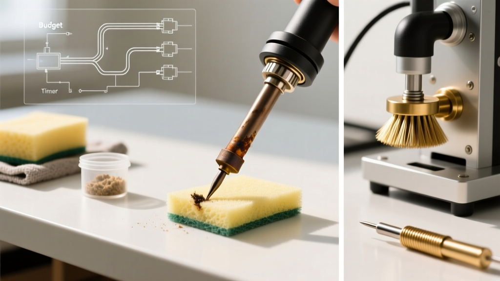
- Cleaning: Always use a damp cellulose sponge or a dry brass wire sponge during operation. Never quench a hot gun tip in water; the thermal shock can snap the copper loop at the terminal bends.
- Dressing: If a bare copper gun tip develops deep pits that prevent heat transfer, you can lightly dress it with a fine-grit flat file while it is completely cold. However, because replacement loops cost between $6 and $9 in 2026, replacing the tip is usually the more reliable choice for maintaining optimal thermal geometry.
- Retorquing: The terminal nuts that hold the copper loop experience intense thermal cycling. Over time, they loosen, introducing electrical resistance at the junction. This resistance generates localized heat, which can melt the phenolic or ABS plastic housing. Check terminal tightness every 20 hours of use using the stamped steel wrench provided in the kit.
Internal Component Repair: Trigger Switches and Transformers
The trigger mechanism on a soldering gun is not a simple light switch; it is a heavy-duty microswitch designed to handle the inductive kickback of a transformer primary coil. When you release the trigger, the collapsing magnetic field in the primary winding generates a high-voltage transient. Over years of use, this causes micro-arcing across the switch contacts, leading to carbon buildup.
Switch Troubleshooting: If your gun requires you to 'pump' the trigger to get it to heat, or if it intermittently cuts out, the switch contacts are likely fouled. Repair Step: Unplug the tool, remove the handle screws, and extract the switch. Use a contact cleaner specifically designed for electrical arcing (e.g., DeoxIT D-Series) and a burnishing tool to polish the contacts. If the plastic toggle is melted or the spring tension is gone, replace the switch block entirely (OEM part numbers vary by model, typically costing $12–$18).
Transformer Failure: The transformer itself rarely fails unless the tool is abused by holding the trigger down continuously for more than 30 seconds. Most high-quality soldering guns feature a duty cycle of roughly 15% to 20%. If you hold the trigger continuously, the primary winding overheats, melting the internal thermal fuse buried deep within the winding wraps. If your multimeter reads an open circuit across the AC plug prongs, and the power cord has tested good for continuity, the thermal fuse has blown. Replacing this fuse requires carefully unwrapping the high-temperature Kapton tape and fiberglass sleeving around the primary coil, splicing in a new 130°C-150°C thermal cutoff, and crimping it securely.
Safety Constraints: When to NEVER Use a Soldering Gun
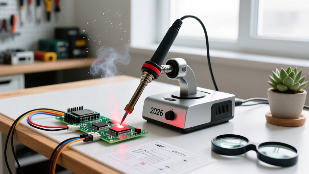
While soldering guns are unmatched for heavy-gauge wire, chassis grounding, and plumbing, they are fundamentally incompatible with modern printed circuit boards (PCBs). According to workmanship and reliability standards outlined by NASA Electronic Parts and Packaging (NEPP) and the IPC (Association Connecting Electronics Industries), transformer-based soldering tools pose severe risks to sensitive solid-state components.
WARNING: Electromagnetic and Stray Voltage Hazards
The single-loop secondary winding of a soldering gun acts as a powerful, localized electromagnet. When the trigger is pulled, a massive AC magnetic field radiates from the tip loop. If brought near a high-impedance circuit, an ungrounded MOSFET gate, or a precision RF trace, this magnetic field can induce enough voltage to punch through thin gate oxides, instantly destroying microcontrollers and logic ICs. Furthermore, the AC voltage present across the tip loop (typically ~0.3V AC) can forward-bias semiconductor junctions if the tip bridges two traces, causing latent damage or immediate short-circuit failures.
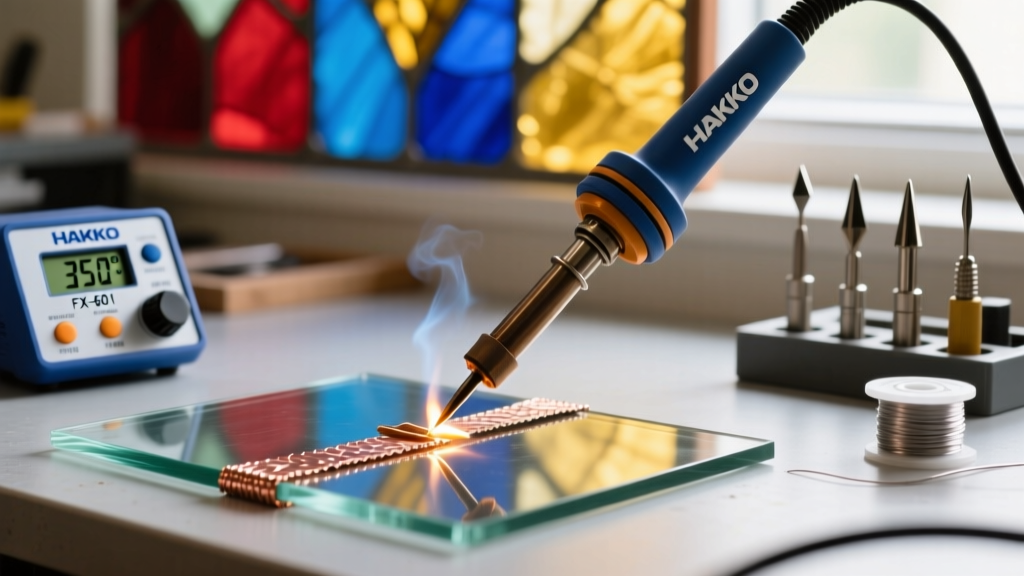
Rule of Thumb for 2026 Electronics: Restrict your soldering iron gun to heavy-duty tasks: soldering 10 AWG to 4 AWG battery cables, joining copper roofing sheets, attaching heavy ring terminals to steel chassis, and stained-glass foil work. For any PCB work, surface-mount devices (SMD), or delicate wiring, always use a temperature-controlled, ESD-safe pencil soldering station with a grounded ceramic heater.
Preventative Maintenance Checklist
To maximize the lifespan of your soldering gun and ensure consistent thermal performance, integrate the following steps into your workshop routine:
- Respect the Duty Cycle: Never hold the trigger for more than 30 seconds. Pull the trigger, heat the joint, flow the solder, and release. Let the magnetic field collapse and the core cool between joints.
- Pre-Tin the Loop: Before storing the gun, always apply a thick layer of 60/40 or 63/37 rosin-core solder to the entire working surface of the copper tip. This sacrificial layer prevents ambient oxidation while the tool sits on the shelf.
- Inspect the Cord Strain Relief: Soldering guns are heavy and often dropped or dragged by the cord. Check the rubber strain relief at the base of the handle for cracking. If the internal SJT cord jacket is exposed, replace the cord immediately to prevent a 120V short against the metal transformer core.
- Lubricate the Trigger Pivot: Apply a microscopic drop of high-temperature synthetic grease to the mechanical pivot point of the plastic trigger to prevent binding and ensure crisp switch actuation.
By understanding the electromagnetic principles and mechanical wear points of your tool, you can keep your soldering iron gun in service for decades, safely tackling the heavy-duty electrical and structural joints that pencil irons simply cannot handle.