
The Anatomy of a Soldering Iron Fine Tip
As surface-mount components shrink to 0201 (0.6mm x 0.3mm) and 01005 (0.4mm x 0.2mm) imperial sizes in 2026, the requirements for precision soldering have evolved dramatically. When engineers and hobbyists search for a soldering iron fine tip solution, they are often met with generic conical attachments that fail under real-world thermal loads. True micro-soldering requires a deep understanding of tip geometry, thermal mass, and sensor integration. A soldering iron fine tip is not merely a scaled-down version of a standard chisel; it is a highly engineered thermal conduit where surface area, plating thickness, and flux dynamics intersect.
According to the IPC J-STD-001 standard for soldered electrical and electronic assemblies, achieving proper wetting and fillet formation on micro-pads requires precise thermal control. If the tip's thermal mass is too low, the joint will cool upon contact, resulting in a cold, grainy solder connection. If the thermal mass is too high, you risk delaminating the PCB pad or destroying the internal die of a micro-BGA component.
Conical vs. Chisel vs. Knife: Which Fine Geometry Wins?
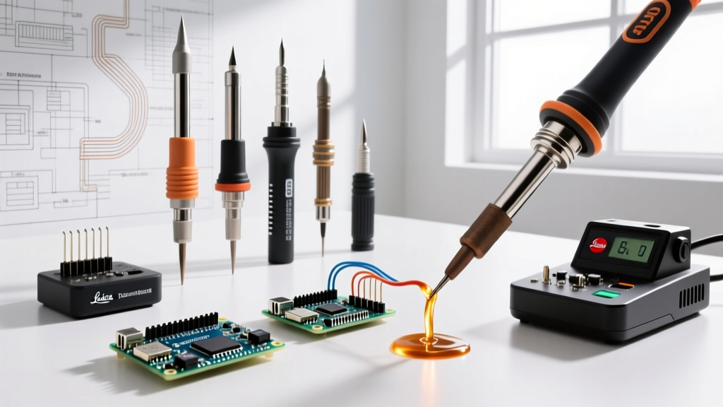
The geometry of your tip dictates capillary action and heat transfer efficiency. Below is a comparison of the three primary micro-tip geometries used in modern SMD rework.
| Tip Geometry | Model Example | Best Application | Thermal Transfer Efficiency |
|---|---|---|---|
| Micro-Conical (B-Type) | Hakko T18-B (0.5mm) | 0402 passives, general fine-pitch | Low (Point contact limits heat flow) |
| Micro-Chisel (D-Type) | Weller RT1 (0.1mm x 0.4mm) | 0.5mm pitch QFP, drag soldering | High (Flat surface maximizes wetting) |
| Micro-Knife (K-Type) | JBC C115-116 (0.3mm) | 0.4mm pitch QFN, corner pin access | Medium-High (Edge and flat versatility) |
Expert Insight: While conical tips seem intuitive for 'fine' work because they look like needles, they actually perform poorly for heat transfer. A micro-chisel or micro-knife provides a flat surface area that bridges the component lead and the PCB pad, allowing solder to flow via capillary action rather than sticking to the tip.
Thermal Recovery and Micro-Joint Heat Transfer
The most critical feature of a soldering iron fine tip setup is the distance between the heating element and the temperature sensor. In legacy stations, the sensor is located deep inside the ceramic heater, while the tip is a separate copper core. This creates a thermal lag. When a 0.1mm tip touches a copper ground plane, the tip temperature plummets, but the sensor doesn't register the drop until seconds later.
Modern active-tip cartridges solve this. In cartridges like the JBC C115 series, the heater, sensor, and tip are integrated into a single micro-cartridge. The sensor sits less than 2 millimeters from the very edge of the tip. This allows the station's microprocessor to detect a temperature drop in milliseconds and pulse the 130W transformer to recover heat before the solder joint solidifies. This rapid recovery is what prevents the 'sticking' phenomenon that plagues cheaper fine-tip irons when attempting to rework fine-pitch ICs.
Real-World Failure Modes: Why Fine Tips Die Early
Fine tips have a notoriously short lifespan if mishandled. Because the copper core is exceptionally thin, it is highly susceptible to specific failure modes:
- Iron Plating Dissolution: Lead-free solder alloys (like SAC305) contain high tin content, which aggressively dissolves the iron plating on the tip. On a 0.1mm tip, the plating layer is microscopic. Leaving the iron at 380°C with lead-free solder on the tip will dissolve the plating in under 4 hours, exposing the copper core to rapid oxidation.
- Thermal Shock Cracking: Wiping a 350°C micro-tip on a damp brass sponge or wet cellulose sponge causes instantaneous thermal contraction. This micro-fractures the iron plating, leading to pitting and non-wetting spots.
- Mechanical Abrasion: Using a fine tip to scrape away oxidized flux or pry up a misaligned 0402 capacitor will physically gouge the plating. Always use a fiberglass scratch pen or isopropyl alcohol for PCB prep, never the tip.
Top Tier Stations for Fine Pitch Work in 2026
If you are building a micro-soldering lab or upgrading your bench, these three stations represent the pinnacle of fine-detail performance, categorized by budget and use-case.
1. The Professional Standard: JBC CD-2BQF with C115 Cartridges
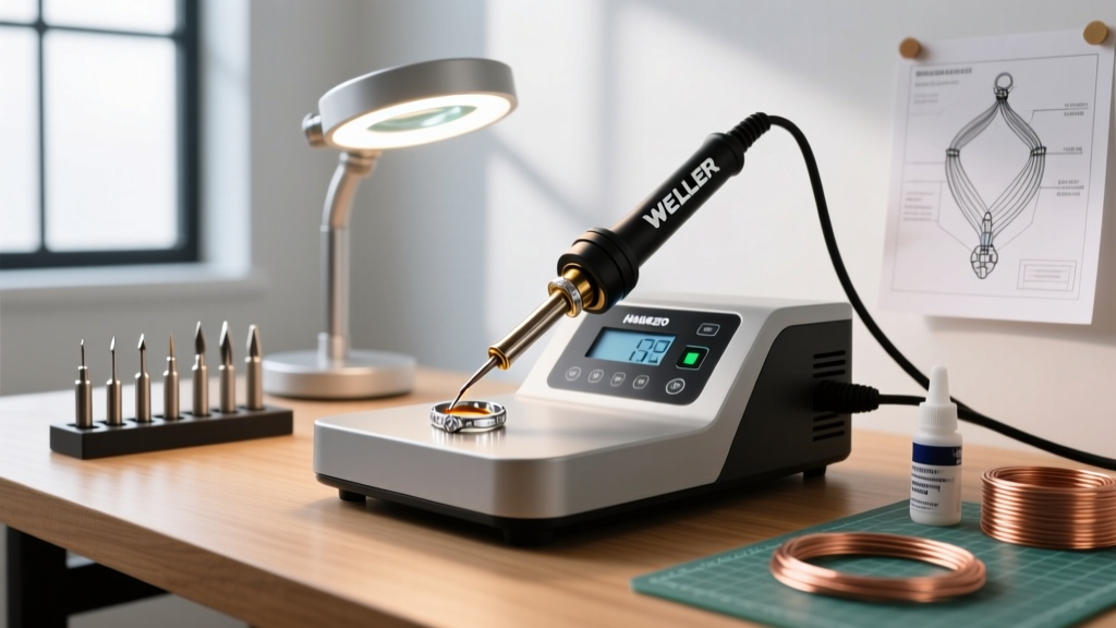
Priced around $620, the JBC CD-2BQF station paired with the NT115 nano-handle is the undisputed king of micro-soldering. The C115-112 (0.1mm conical) and C115-116 (0.3mm knife) tips heat from standby to 350°C in just 2 seconds. The ultra-lightweight handle reduces hand fatigue during long sessions under a microscope, and the sleep stand automatically drops the tip to 180°C when holstered, extending tip life by up to 500%.
2. The Reliable Workhorse: Hakko FX-951 with T18 Series
At approximately $330, the Hakko FX-951 remains a staple in manufacturing environments. While its T18-B (0.5mm) and T18-I (0.2mm) tips are slightly larger than JBC's nano offerings, they are incredibly robust and cost under $10 each. The FX-951 uses a composite sensor design that offers excellent thermal recovery for 0402 and 0.5mm pitch SOIC packages, making it ideal for high-volume repair benches.
3. The Open-Source Contender: Pine64 Pinecil V2
For hobbyists and field technicians, the $26 Pinecil V2 is a marvel of engineering. Powered by the Bouffalo Lab BL706 RISC-V chip, it supports TS100-compatible tips. By pairing it with a micro-chisel tip and a 65W USB-C PD power supply, you can achieve remarkable fine-pitch results. While it lacks the instantaneous thermal mass recovery of a JBC, its PID tuning algorithm handles 0603 and 0402 SMD components with ease.
Step-by-Step: Soldering 0.4mm Pitch QFN Chips
Soldering a 0.4mm pitch QFN (Quad Flat No-leads) package requires strict adherence to process control. The NASA-STD-8739.3 workmanship manual emphasizes the necessity of flux in achieving reliable micro-joints. Here is the exact procedure used by professional rework technicians:
- Pad Preparation: Clean the PCB pads with 99% isopropyl alcohol. Apply a microscopic layer of tacky flux (e.g., Amtech NC-559-V2-TF) using a syringe with a 22-gauge needle. Do not flood the pads; excess flux will cause solder bridging.
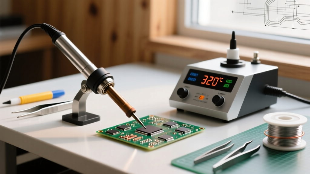
- Pre-Tinning: Using a micro-chisel tip set to 320°C (for Sn63/Pb37) or 350°C (for SAC305), apply a tiny amount of 0.3mm diameter solder wire to the pads. The goal is a flat, even layer, not a dome.
- Component Alignment: Place the QFN chip using fine-point tweezers under a stereo microscope. Ensure the pin-1 indicator aligns perfectly with the PCB silkscreen.
- Corner Tacking: Touch two opposite corner pins with the iron to lock the component in place. Verify alignment from all four sides before proceeding.
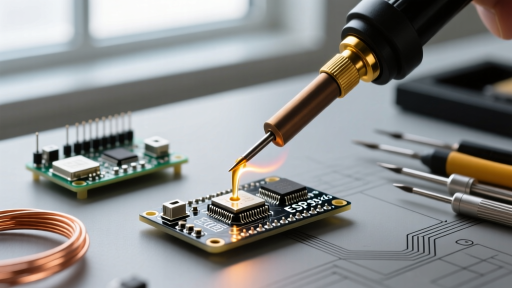
- Perimeter Soldering: Switch to a micro-knife tip. Apply fresh liquid or gel flux to the entire perimeter. Drag the knife tip along the pins at a 45-degree angle. The flux will break the surface tension of the solder, pulling it away from the gaps and preventing bridges.
- Inspection and Cleanup: Inspect under 40x magnification for any micro-bridges. If a bridge exists, do not panic. Apply more flux and use a clean, dry micro-knife tip to 'wick' the excess solder away, or use 0.5mm desoldering braid.
FAQ: Fine Soldering Iron Troubleshooting
Why does my solder ball up on the fine tip instead of flowing to the pad?
This is a classic wetting failure caused by oxidation or insufficient flux. Fine tips have a high surface-area-to-volume ratio, meaning they oxidize faster in ambient air. Always keep a small bead of solder on the tip when returning it to the stand. If the tip is already oxidized, use a chemical tip tinner (like Hakko 599B) rather than sandpaper, which will permanently destroy the iron plating.
Can I use a fine tip for desoldering through-hole components?
No. Fine tips lack the thermal mass required to heat the inner barrel of a plated through-hole (PTH). Attempting to use a 0.2mm tip on a PTH will result in prolonged heating, which will lift the copper annular ring off the fiberglass substrate. Always switch to a high-mass chisel or a dedicated desoldering gun for through-hole work.
What is the ideal solder wire diameter for fine tip work?
For 0402 components and 0.5mm pitch ICs, use 0.3mm (0.012 inch) diameter solder wire. For 0201 and 01005 components, traditional wire is too thick; instead, use solder paste applied via a syringe, or pre-tin the pads and rely solely on the flux to reflow the existing solder.
Mastering a soldering iron fine tip setup bridges the gap between amateur repairs and professional-grade micro-electronics manufacturing. By respecting tip geometry, managing thermal dynamics, and utilizing high-quality flux, you can reliably assemble and rework the most complex SMD designs on the market.