
Unlocking the Thermal Potential of the FX-951 Platform
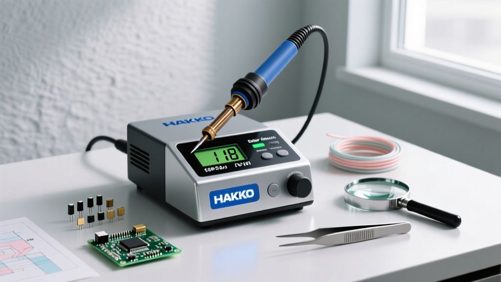
The Hakko soldering station FX 951 66 represents a benchmark in professional ESD-safe soldering, widely adopted by both high-volume manufacturing floors and advanced DIY electronics labs. Unlike older analog or basic digital stations that rely on a separate ceramic heater and a hollow sleeve tip, the FX-951 utilizes a composite heating element. In this design, the heater, sensor, and tip are integrated into a single T18 cartridge. This architecture reduces thermal resistance to near zero, allowing the 70-watt power supply to recover from thermal drops in under a second.
As of 2026, the FX-951-66 configuration—often distributed as a specialized regional or ESD-compliant kit bundle—remains a top-tier choice, with market pricing generally hovering between $260 and $295. However, owning high-end equipment is only half the battle. Achieving IPC-compliant solder joints requires a deep understanding of thermal profiling, tip geometry, and advanced application techniques. This guide bypasses basic soldering theory to focus strictly on high-level techniques tailored to the FX-951's unique thermal delivery system.
Temperature Profiling Matrix for Modern Alloys
A common failure mode among technicians is setting the station to a static 350°C (662°F) regardless of the solder alloy or PCB thermal mass. The FX-951's rapid recovery means you can actually run lower baseline temperatures than older stations, minimizing flux burn-off and pad delamination. According to the IPC J-STD-001 standard, thermal excursion times must be tightly controlled to prevent component damage.
| Solder Alloy | Composition | Melting Point | Optimal FX-951 Temp | Max Dwell Time |
|---|---|---|---|---|
| Standard Leaded | Sn63/Pb37 | 183°C (361°F) | 310°C - 330°C | 2 - 4 seconds |
| Lead-Free (Standard) | SAC305 (Sn96.5/Ag3/Cu0.5) | 217°C (423°F) | 350°C - 370°C | 3 - 5 seconds |
| Low-Temp Bismuth | Sn42/Bi57 | 138°C (280°F) | 220°C - 240°C | 2 - 3 seconds |
| High-Reliability | Sn95/Sb5 | 235°C (455°F) | 360°C - 380°C | 3 - 5 seconds |
Note: Always increase the temperature by 10°C to 15°C when working on multi-layer PCBs with heavy internal copper ground planes, as the thermal draw will outpace the sensor's localized reading.
Strategic T18 Tip Selection
The T18 tip ecosystem is vast, but mastering the FX-951 requires restricting your daily rotation to the most thermally efficient geometries. The official Hakko USA documentation outlines dozens of variants, but the following four are essential for advanced surface-mount and through-hole rework:
- T18-D24 (Chisel, 2.4mm): The workhorse for 0805 and 0603 passive components, as well as standard through-hole leads. The flat blade maximizes surface area contact, ensuring rapid heat transfer without requiring excessive downward pressure.
- T18-K (Knife): The undisputed champion for drag soldering fine-pitch QFP and SOIC integrated circuits. The angled edge allows you to use the point for precision tacking and the flat blade for dragging solder across dozens of pins simultaneously.
- T18-IL (Micro-Conical, 0.2mm): Reserved exclusively for ultra-fine-pitch 0201 passives and micro-BGA rework. Warning: This tip has very low thermal mass; it will stall instantly on ground planes. Use only on isolated, low-mass pads.
- T18-C4 (Bevel, 4.0mm): Ideal for tinning heavy-gauge wires (14 AWG to 10 AWG) and soldering large mechanical tabs. The concave bevel holds a pool of molten solder, enveloping the wire strand for complete capillary wicking.
Advanced Technique: Drag Soldering Fine-Pitch QFP ICs
Drag soldering is a high-speed technique that leverages the surface tension of molten solder and the flux's chemical properties to automatically align and bond fine-pitch pins. The FX-951's instant thermal recovery makes it uniquely suited for this, as the tip does not cool down mid-drag.
- Preparation: Apply a generous layer of high-quality tacky flux (e.g., Amtech NC-559 or ChipQuik SMD291) to the bare PCB pads. Align the QFP IC and tack two opposite corner pins using the point of the T18-K knife tip at 340°C.
- Solder Loading: Melt a small bead of 0.5mm diameter Sn63/Pb37 (or SAC305) solder directly onto the edge of the T18-K blade. You want a continuous 'wave' of solder, not a massive blob.
- The Drag: Tilt the handpiece to a 45-degree angle. Place the solder wave against the first pin of the IC. Slowly drag the tip across the pins at a rate of roughly 1 inch per second. Let the flux do the work—the surface tension will pull the solder onto the pads and away from the gaps.
- Managing Bridges: If a solder bridge forms between two pins, do not panic and do not use the iron to 'wipe' it away. Apply a small amount of fresh liquid flux, clean the tip on a damp brass sponge, and drag the clean, hot tip across the bridge. The flux will break the surface tension, and the clean tip will absorb the excess solder.
- Inspection: Clean the board with 99% isopropyl alcohol and inspect under a 10x loupe or digital microscope to ensure complete wetting and no micro-bridges.
Overcoming High Thermal Mass Edge Cases
Expert Insight: When soldering a capacitor to a solid copper ground plane on a 4-layer PCB, the plane acts as an infinite heat sink. If you press harder with a small tip, you will only damage the pad. Instead, switch to a T18-D32 or T18-C4 tip, raise the FX-951 to 380°C, and apply heat to the plane, not just the component lead.
For extreme thermal mass scenarios where even the T18-C4 stalls, the FX-951-66 kit's 70W output may reach its limit. In these edge cases, you must introduce supplemental thermal energy. Using a PCB pre-heater (like the Hakko FR-820) set to 120°C reduces the temperature delta the iron must overcome. This allows you to drop the iron's temperature back to a safer 340°C, preserving the lifespan of your T18 tip and preventing the PCB's FR4 substrate from exceeding its glass transition temperature (Tg), which can cause internal delamination.
Maintenance, Calibration, and ESD Safety
The FX-951 is an ESD-safe station, meaning the handpiece and tip are electrically grounded to the station's chassis, and subsequently to earth ground via the power cord. This is critical when handling MOSFETs and bare CMOS ICs. To verify this, use a multimeter to check the resistance between the tip and the grounding pin on the plug; it should read less than 2 ohms.
Furthermore, the integrated sensor in the T18 cartridge can drift over time due to repeated thermal cycling. According to guidelines referenced in advanced electronics assembly resources like the Adafruit Excellent Soldering Guide, periodic verification is essential. Every six months, use a Hakko 191 or 192 digital thermometer with a K-type thermocouple to measure the actual tip temperature. If the deviation exceeds ±5°C from the digital readout, use the station's internal offset calibration mode (accessed via the front-panel push-button sequence detailed in the service manual) to realign the sensor data.
Final Thoughts on Technique Mastery
The Hakko soldering station FX 951 66 is an investment in thermal precision. By abandoning static temperature habits, matching your T18 tip geometry to the specific thermal mass of the joint, and leveraging the station's sub-second recovery for advanced techniques like drag soldering, you elevate your work from amateur assembly to professional-grade manufacturing. Treat the tip as a consumable thermal bridge, keep it tinned, and let the station's 70-watt induction architecture do the heavy lifting.