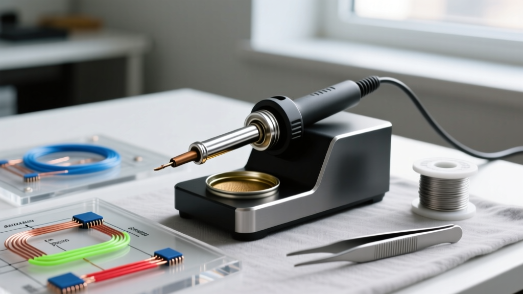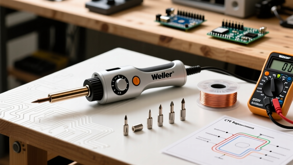

Introduction to Soldering Station Architecture
Whether you are repairing a vintage Weller WESD51, upgrading a Hakko FX-951, or building a custom PID-controlled rig in 2026, hobbyists and professionals alike often overlook the internal architecture of their tools. The market is saturated with complete, plug-and-play kits, but true thermal mastery requires a deep understanding of individual soldering iron components. From the heating element topology to the metallurgical layering of the tip, each component dictates thermal recovery time, oxidation resistance, and overall joint reliability.
This guide compares the most critical internal architectures—heating elements, tip metallurgy, thermal sensors, and power delivery topologies—to help you make informed hardware decisions, troubleshoot thermal lag, and extend the lifespan of your equipment.
The Core Debate: Ceramic vs. Nichrome vs. Induction Heaters
The heating element is the heart of the iron. It converts electrical energy into thermal energy, and its physical design determines how quickly heat transfers to the tip and the working surface. According to Hackaday's comprehensive hardware analysis, the three dominant heater technologies each possess distinct failure modes and thermal profiles.
1. Ceramic Heaters (e.g., Hakko A1321)
Ceramic elements utilize printed resistive tracks on an alumina substrate. They are the standard in modern mid-range stations like the Hakko FX-888D.
- Pros: Extremely fast heat-up times (often reaching 350°C in under 20 seconds), compact form factor, and excellent electrical isolation.
- Cons: High mechanical fragility. Dropping the handpiece or applying excessive lateral torque when cleaning the tip can crack the ceramic core, instantly killing the element. Furthermore, the integrated thermistor can drift over time if subjected to repeated thermal shock.
2. Nichrome Wire-Wound Elements (e.g., Weller PES51)
Nichrome (Nickel-Chromium) wire is tightly wrapped around a ceramic or mica core. This is the legacy architecture found in heavy-duty industrial irons like the Weller WES51.
- Pros: Exceptional ruggedness and high thermal mass. They survive mechanical shock and physical abuse that would shatter a ceramic element.
- Cons: Slower thermal recovery and higher thermal lag. The sensor is often physically separated from the heater wire, leading to a slight delay in PID feedback loops during heavy ground-plane soldering.
3. RF Induction / Curie Point (e.g., Metcal STTC Series)
Induction systems do not use a traditional resistive heater. Instead, an RF generator (typically operating at 13.56 MHz or 470 kHz) induces eddy currents directly into the ferromagnetic tip.
- Pros: Instantaneous thermal recovery and self-regulating temperature. The tip itself acts as both the heater and the sensor.
- Cons: High cost of both the base station and the proprietary tips. The RF field can occasionally interfere with highly sensitive, unshielded RF prototyping circuits on the bench.
Component Comparison Matrix
| Feature | Ceramic (Hakko A1321) | Nichrome (Weller PES51) | Induction (Metcal STTC) |
|---|---|---|---|
| Heat-Up Time (to 350°C) | ~18 Seconds | ~45 Seconds | ~8 Seconds |
| Mechanical Durability | Low (Brittle) | High (Rugged) | Medium (Tip dependent) |
| Thermal Recovery | Good (PID dependent) | Moderate (Thermal lag) | Exceptional (Instant) |
| Average Replacement Cost | $12 - $18 USD | $25 - $35 USD | N/A (Tip is the heater) |
Tip Metallurgy and Plating Architecture
A common misconception is that a soldering tip is simply a shaped piece of copper. In reality, modern tips are complex, multi-layered composites engineered to balance thermal conductivity with chemical resistance. Understanding these soldering iron components is vital when transitioning between leaded and lead-free workflows.
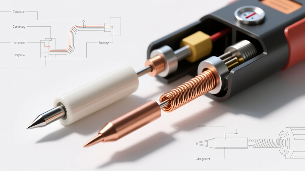
The Anatomy of a Modern Tip
- OFHC Copper Core: Oxygen-Free High Thermal Conductivity copper forms the bulk of the tip, rapidly drawing heat from the element to the joint.
- Nickel Barrier Layer: A thin nickel strike prevents the molten solder from dissolving the copper core—a process known as leaching.
- Iron Plating: The working surface is plated with iron, typically between 100 and 150 microns thick. Iron resists oxidation and prevents the solder from alloying with the tip itself.
- Wetting Layer: The very tip of the iron plating is tinned with a micro-layer of solder to facilitate immediate heat transfer upon contact.
Critical Edge Case: Lead-Free Tip Degradation
When working with SAC305 (Sn96.5/Ag3.0/Cu0.5) lead-free alloys, the high tin content aggressively leaches iron from the tip at the elevated temperatures required (350°C+ compared to 315°C for Sn63/Pb37). According to the IPC J-STD-001 standards for soldered assemblies, maintaining strict thermal profiles is mandatory to prevent joint defects. Exceeding 380°C with SAC305 will cause rapid tip pitting, cratering, and dewetting, effectively destroying a $10 tip in a matter of hours. Always use specialized lead-free tips with thicker iron plating (up to 250 microns) when working with high-tin alloys.
Thermal Feedback Sensors: How the Station 'Thinks'
The heater provides the muscle, but the sensor provides the brains. The closed-loop feedback system relies on accurate temperature data to maintain the setpoint.
Thermocouples (Type K and Type J)
Often found in older or heavy-duty industrial stations, thermocouples generate a micro-voltage proportional to the temperature differential between the hot junction (at the tip) and the cold junction (inside the handpiece). They are incredibly robust but require complex cold-junction compensation circuitry on the mainboard to remain accurate.
PTC Thermistors
Positive Temperature Coefficient thermistors are the standard in modern ceramic heaters like the Hakko T18 series. Their electrical resistance increases predictably as temperature rises. They are highly sensitive and offer rapid response times, making them ideal for fast-switching PID controllers. However, they are vulnerable to thermal runaway if the wiring harness develops a high-resistance fault, which the controller may misinterpret as a 'cold' tip.
The Curie Point Phenomenon
In induction systems, the sensor is entirely eliminated. The ferromagnetic alloy of the tip is engineered to lose its magnetic properties at a specific temperature (the Curie point, e.g., 350°C for an STTC-135 tip). Once the tip reaches this temperature, the RF field can no longer induce eddy currents, and heating stops instantly. As soon as the tip loses heat to the PCB pad, it drops below the Curie point, regains magnetism, and heating resumes. This provides the most stable thermal profile available in 2026.
Power Delivery: Toroidal vs. GaN Switch-Mode
The power supply dictates how much sustained wattage can be delivered to the heating element during high-thermal-mass operations, such as soldering large ground planes or heavy gauge wire.
- Toroidal Transformers: Traditional stations use heavy, 50Hz/60Hz toroidal transformers. They provide clean, isolated AC power with massive surge current capabilities, but they add significant weight and bulk to the bench.
- GaN Switch-Mode Power Supplies (SMPS): In 2026, Gallium Nitride (GaN) technology has revolutionized portable soldering. Tools like the Pinecil V2 utilize GaN-based SMPS to draw up to 65W-100W via USB-C PD (Power Delivery). These components offer incredible power density, allowing a station that fits in a pocket to rival the thermal recovery of a benchtop Weller WXD2.
Frequently Asked Questions (FAQ)
Can I mix and match tips and heaters across different brands?
No. Soldering iron components are rarely cross-compatible. A Hakko T18 tip is designed to slide over a specific ceramic heater sleeve with exact mechanical tolerances. Attempting to force it onto a Weller PES51 element will result in poor thermal transfer, mechanical damage to the ceramic core, and potential electrical shorts.
Why do my tips turn black and refuse to accept solder?
This is caused by flux carbonization and iron oxidation. When rosin-based flux (RMA) is subjected to temperatures above 360°C, it burns into a hard carbon crust. Simultaneously, the iron plating oxidizes, creating a barrier that solder cannot wet. To fix this, never use abrasive sandpaper or files, which will strip the 100-micron iron plating and expose the copper core to immediate destruction. Instead, use a brass wire sponge and a specialized tip tinner/cleaner compound containing mild acids and fresh solder powder.
How do I calibrate the thermal sensor on my station?
Most modern digital stations (like the Hakko FX-951) feature a digital offset calibration menu. Using a high-accuracy K-type thermocouple probe and a specialized tip thermometer (such as the Hakko FG-100), you can measure the actual surface temperature of the tip and input the offset value into the station's firmware to correct for sensor drift over time.