
The Thermodynamic Reality of Emergency Soldering
The concept of the makeshift soldering iron is deeply romanticized in electronics lore. From apocalyptic survival scenarios to a late-night lab crisis when your primary Weller or Hakko station dies, the idea of MacGyvering a heating element to melt solder feels like a rite of passage. However, the transition from a red-hot piece of metal to a functional soldering tool is governed by strict laws of thermodynamics and metallurgy. In 2026, with the widespread adoption of complex lead-free alloys and dense PCB ground planes, the margin for error with improvised tools is razor-thin.
To understand why most DIY soldering irons fail, we must distinguish between temperature and thermal energy. A thin steel nail heated by a lighter may reach 400°C (752°F), easily surpassing the melting point of standard Sn63/Pb37 eutectic solder (183°C). Yet, the moment it touches a copper pad, its temperature plummets because it lacks the thermal mass and continuous heat input required to overcome the thermal conductivity of the PCB. The result is a cold, grainy, and unreliable solder joint.
Core Metrics: Thermal Mass vs. Thermal Recovery
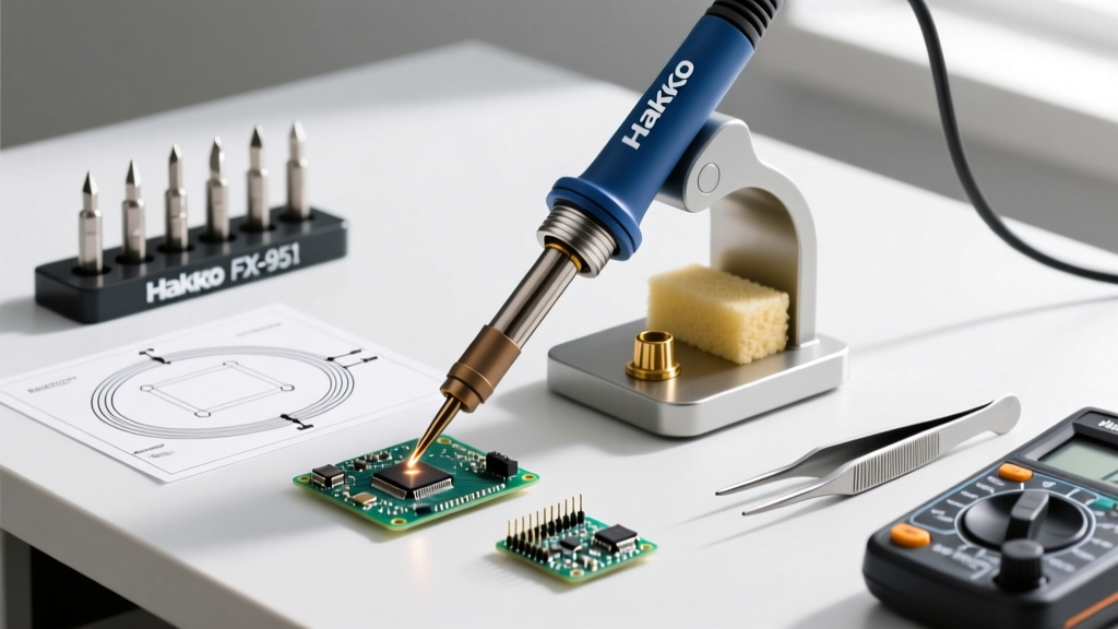
A professional soldering station, like a Hakko FX-951, utilizes a closed-loop thermocouple or Curie-point sensor to maintain tip temperature by injecting wattage precisely when heat is drawn away by the joint. A makeshift iron lacks this feedback loop. Therefore, a successful improvised iron must rely on brute-force thermal mass or a carefully calculated continuous power draw.
- Thermal Mass: The ability of the tip material to store heat. Copper is the gold standard (specific heat capacity of 0.385 J/g°C), while steel is significantly less efficient.
- Thermal Recovery: How fast the heat source can replenish the energy lost to the PCB ground plane. Without active recovery, the tip temperature drops below the liquidus point of the solder, causing premature solidification and wetting failure.
Three Common Makeshift Builds (And Their Engineering Flaws)
Build 1: The Wirewound Power Resistor Heater
This is the most electrically sound makeshift soldering iron you can build. By utilizing a high-wattage ceramic wirewound resistor, you create a stable heating core.
- Components: A 5-ohm, 50W ceramic wirewound resistor, a length of bare 12 AWG solid copper wire, and a DC power supply.
- The Math: Using Ohm's Law (P = V²/R), applying 15V DC across a 5-ohm resistor yields 45 Watts of continuous heat dissipation.
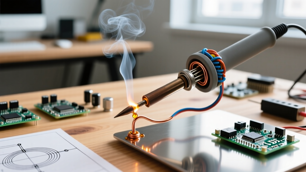
- Assembly: Tightly wrap the 12 AWG copper wire around the resistor body to act as the thermal transfer tip. Secure it with high-temp stainless steel safety wire (do not use aluminum or copper tie-wire, as they will anneal and loosen under heat).
- The Flaw: The thermal transfer from the ceramic core through the air gaps to the copper tip is inefficient. It requires a 3-minute preheat time, and the exposed copper will oxidize rapidly if not immediately tinned with a heavy layer of rosin-core solder.
Build 2: The Open Flame and Copper Core
Often attempted with a butane torch or alcohol lamp, this method uses a thick piece of 8 AWG or 6 AWG solid copper wire as both the heater and the tip.
The Metallurgical Failure Mode: Copper oxidizes aggressively when exposed to open flames and high ambient heat. Above 200°C, copper forms cupric oxide (CuO), a black, crusty layer that solder absolutely will not wet to. While chemical flux can dissolve CuO, the extreme, unregulated heat of a torch (often exceeding 800°C at the core) instantly vaporizes and carbonizes standard rosin flux before it can clean the metal. You are left with a blackened, unwettable club that pushes molten solder around like water on a greased pan.
Build 3: The USB Short-Circuit (The Danger Zone)
A notorious internet hack involves stripping a USB cable, shorting the 5V VBUS to Ground through a paperclip or thin nichrome wire, and relying on the resistance to generate heat. Do not do this. Standard USB 2.0 ports limit current to 500mA (2.5W max). Even a USB 3.0 port at 900mA only yields 4.5W. This is vastly insufficient for soldering. Furthermore, intentionally shorting a power bus risks destroying the host motherboard's power delivery IC or triggering a lithium-polymer battery fire if connected to a portable power bank lacking proper short-circuit protection.
The 2026 Modern Twist: USB-C PD Decoy Triggers
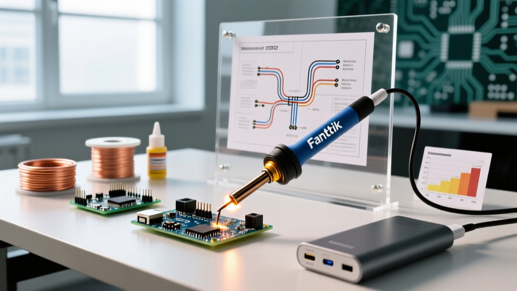
If you must build an emergency electric iron in the modern era, abandon raw USB shorts and use a USB-C Power Delivery (PD) decoy board. These $3 PCBs can be configured to request 20V at 3A (60W) from any modern laptop charger or PD power bank. By connecting the 20V output to a properly rated resistive heating element (like a salvaged ceramic heater from a broken 3D printer hotend or a high-wattage power resistor), you create a highly capable, relatively safe 60W makeshift soldering iron that rivals entry-level commercial stations in raw thermal output.
Makeshift Iron Comparison Matrix
| Build Type | Max Free-Air Temp | Thermal Recovery | Oxidation Risk | Safety Hazard Level |
|---|---|---|---|---|
| Wirewound Resistor (50W) | ~380°C | Moderate (15-20s) | High (Tip) | Low (Burn risk only) |
| Torch + Copper Wire | 800°C+ | High (Continuous) | Extreme (CuO buildup) | High (Fire/Fume risk) |
| USB-C PD + Ceramic Heater | ~350°C | Excellent (Closed-loop potential) | Moderate | Low (If properly insulated) |
| LiPo + Nichrome Short | Variable (Often melts) | Poor (Voltage sag) | High | Critical (Thermal Runaway) |
Safety Protocols: Fumes, Fire, and Toxicity
When operating outside the controlled environment of a proper lab with an active fume extractor, makeshift soldering introduces severe health and safety risks. According to Adafruit's comprehensive soldering safety guide, the primary danger is not the lead in the solder, but the flux. Heating rosin-based (colophony) flux generates aliphatic aldehydes and acidic gases that are known sensitizers, capable of triggering occupational asthma and severe respiratory irritation.
Furthermore, if your makeshift build involves melting the PVC insulation off copper wires using a flame or unregulated resistor, you are releasing hydrogen chloride gas and potentially dioxins into your breathing zone. Always operate improvised soldering setups outdoors or in front of an active exhaust fan. For detailed protocols on mitigating heavy metal and chemical exposure, refer to the Hakko soldering safety documentation, which outlines the necessity of HEPA and activated carbon filtration when handling vaporized flux compounds.
The Verdict: When to DIY and When to Walk Away
The Field-Repair Decision Matrix:
Use a makeshift soldering iron ONLY for: Large through-hole components, heavy-gauge wire splices, and non-critical, low-frequency connections where a bulky, messy joint is acceptable.
ABORT the makeshift attempt and wait for proper tools if you are dealing with: Surface Mount Devices (SMD) smaller than 0805, multi-layer PCBs with internal ground planes (which will act as massive heat sinks and wick away all your thermal energy), or any RF/high-speed digital traces where excess solder capacitance or cold-joint resistance will destroy signal integrity.
Ultimately, a makeshift soldering iron is a tool of desperation, not innovation. By understanding the thermodynamic limits of your improvised heater and respecting the metallurgical requirements of modern solder alloys, you can successfully execute an emergency repair without destroying the board—or your lungs—in the process.