
The Physics of Wattage: Why 100W Matters
In the electronics and DIY community, a pervasive myth continues to mislead beginners: the belief that higher wattage equates to higher maximum temperatures. When you evaluate a soldering iron 100w configuration, you are not looking at a tool designed to melt solder faster by sheer heat intensity. Instead, you are looking at a tool engineered for thermal recovery rate and thermal mass management.
Wattage is a measure of power consumption and energy transfer over time (Joules per second). A standard 45W soldering station can easily reach 400°C (752°F) at the tip in an open-air state. However, the moment that tip touches a massive copper ground plane or a thick 10 AWG silicone wire, the joint acts as a giant heat sink. The copper rapidly conducts heat away from the tip (copper boasts a thermal conductivity of roughly 401 W/m·K). A 45W iron lacks the continuous energy output to replenish the lost heat, causing the tip temperature to stall or plummet. This results in prolonged dwell times, cold solder joints, and catastrophic pad delamination.
The Golden Rule of Thermal Mass: Wattage does not determine how hot the iron gets; it determines how fast the iron recovers its temperature when heat is aggressively siphoned away by the workpiece.
According to the IPC-A-610 standard for electronic assemblies, prolonged dwell times caused by underpowered irons are a primary culprit for hidden thermal damage to components and PCB substrates. A 100W iron pushes a continuous wall of thermal energy into the joint, achieving the required solder flow in seconds rather than minutes.
Thermal Mass vs. Temperature: The Core Misconception
To understand why a high-wattage tool is mandatory for specific tasks, we must differentiate between low, medium, and high thermal mass joints. In 2026, with the rise of high-density multi-layer PCBs and heavy-duty drone/robotics wiring, managing thermal mass is more critical than ever. Furthermore, NASA Workmanship Training guidelines explicitly warn against exceeding maximum dwell times on terminals, a risk that skyrockets when using underpowered irons on heavy joints.
| Joint Type | Thermal Mass | 45W Iron Recovery | 100W Iron Recovery | Risk of Pad/Insulation Damage |
|---|---|---|---|---|
| 0805 SMD Pad | Low | < 1.5 sec | < 0.5 sec | Low (if temp controlled) |
| 16 AWG Wire to Pin | Medium | 4-6 sec | 1-2 sec | Moderate |
| 10 AWG to XT90 Brass Cup | High | 15+ sec (Stalls) | 3-4 sec | High with 45W (melts silicone) |
| Multi-layer GND Plane Via | Extreme | Fails to melt | 5-7 sec | Extreme with 45W (barrel cracking) |
Real-World Applications for a Soldering Iron 100W Setup
While a 65W smart iron (like the popular USB-C PD models) handles 90% of standard PCB work, a dedicated 100W setup is indispensable for specific heavy-duty scenarios:
- High-Current RC and Drone Wiring: Soldering 10 AWG to 8 AWG silicone wires into XT90, AS150, or QS8 connectors. The brass cups in these connectors absorb massive amounts of heat.
- Stained Glass and Copper Foil: The Tiffany method requires running continuous, smooth beads of 60/40 solder along copper tape. A 100W iron maintains a stable temperature across long, continuous draws without stuttering.
- Automotive and Marine Harnesses: Soldering heavy gauge wires to large ring terminals or alternator posts where the ambient metal mass is enormous.
- Heavy Ground Plane Rework: Desoldering multi-pin connectors that are anchored to large copper pours on a motherboard or power supply unit (PSU).
Equipment Breakdown: Generic 100W vs. Smart High-Wattage
Not all 100W irons are created equal. The market is currently split between traditional high-wattage pencil irons and modern cartridge-based systems.
The Generic 100W Pencil Iron
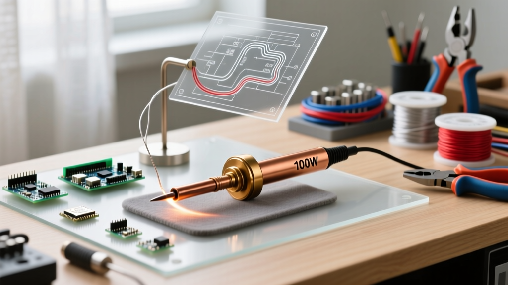
The ubiquitous "100W adjustable" irons found on general marketplaces typically use a mica-wound nichrome heating element wrapped around a hollow ceramic tube. While they deliver raw power, they suffer from severe thermal lag. The sensor is located deep inside the heater, not at the tip. When you touch a cold XT90 connector, the tip temperature drops, but the sensor doesn't register the loss immediately. By the time the heater kicks into overdrive, the tip has oxidized, and the flux has carbonized. These are acceptable for stained glass or plumbing, but highly discouraged for precision electronics.
The Modern Cartridge Alternative (JBC / Weller RT)
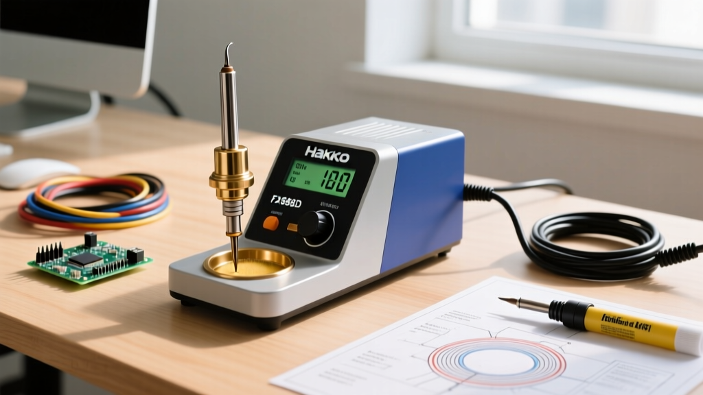
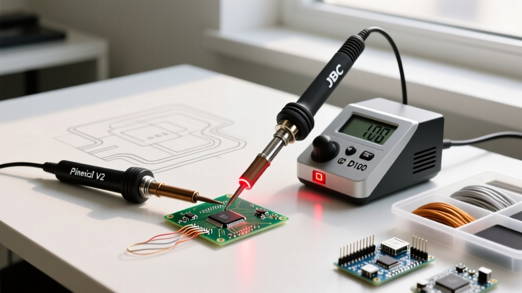
The professional evolution of the "100W requirement" is the integrated cartridge system. Brands like JBC (C245 handles) and Weller (RT series) embed the thermocouple directly inside the tip, millimeters from the contact surface. While a JBC CD-2B station might output 130W, the closed-loop feedback reacts in milliseconds. As Hakko's official technical resources and other industry leaders have demonstrated, a highly efficient 67W to 80W ceramic heater (like the Hakko FX-601 or Weller WE1010) with a massive chisel tip will often outperform a cheap, unregulated 100W iron because of superior thermal transfer efficiency and zero thermal lag.
Step-by-Step: Soldering an XT90 Connector with High Wattage
Soldering an anti-spark XT90 connector is the ultimate test of thermal management. Using a 100W iron with a wide chisel tip (e.g., 6mm or larger), follow this precise methodology to avoid melting the silicone wire insulation or the plastic connector housing.
- Mechanical Preparation: Strip exactly 7mm of silicone insulation from the 10 AWG wire. Twist the strands tightly, then fold the wire back on itself (fluting) to create a compact, flat bundle that matches the depth of the brass cup.
- Flux Application: Apply a high-tack, no-clean gel flux (such as Amtech NC-559 or MG Chemicals 8341) to both the wire bundle and the inside of the brass cup. Do not use liquid flux; it will boil away before the thermal mass is overcome.
- Pre-Tinning the Wire: Hold the wire vertically. Apply the 100W iron to the wire and feed SAC305 or 63/37 solder until the strands are fully wicked. The high wattage will melt the solder into the core of the wire in under 3 seconds.
- The Brass Cup Fill: Hold the XT90 connector with a helping-hands fixture. Insert the pre-tinned wire into the cup. Apply the wide chisel tip so it bridges the edge of the brass cup and the tinned wire simultaneously.
- The 3-Second Rule: Feed solder directly into the joint, not onto the iron tip. The 100W thermal recovery will instantly reflow the pre-tinned wire and the cup together. Remove heat the moment the solder meniscus dips slightly (indicating full capillary penetration). Total dwell time should not exceed 4 seconds.
Frequently Asked Questions
Will a 100W iron burn my PCB pads?
Only if it lacks temperature regulation or if you use the wrong tip geometry. Heat transfer is dictated by surface area contact. A 100W iron with a fine conical tip will force you to press harder and dwell longer, transferring heat poorly and risking pad lift. A 100W iron with a wide bevel or chisel tip, set to 320°C (608°F), will transfer the necessary energy in two seconds, which is entirely safe for standard FR-4 fiberglass substrates.
Can I use a 100W iron for SMD components?
It is highly discouraged unless you are using a modern, digitally regulated smart station with a micro-tip cartridge. Traditional 100W irons have massive thermal overshoot when not in contact with a joint. If you set a generic 100W iron to 300°C, the open-air tip temperature can easily spike to 450°C between joints, instantly destroying the internal die of sensitive SMD ICs and burning the flux into a non-conductive, corrosive carbon shell.
Why does my 100W iron tip turn black and stop wetting?
This is a classic symptom of thermal overshoot and flux carbonization. High-wattage irons cycle their heating elements aggressively. If you leave the iron in its holder without a standby/sleep function, the tip oxidizes rapidly. Always tin the tip heavily with a blob of cheap 60/40 solder before placing it in the holder; this sacrificial solder layer will oxidize instead of the iron plating on the tip itself.