
Why Build a DIY Soldering Iron?
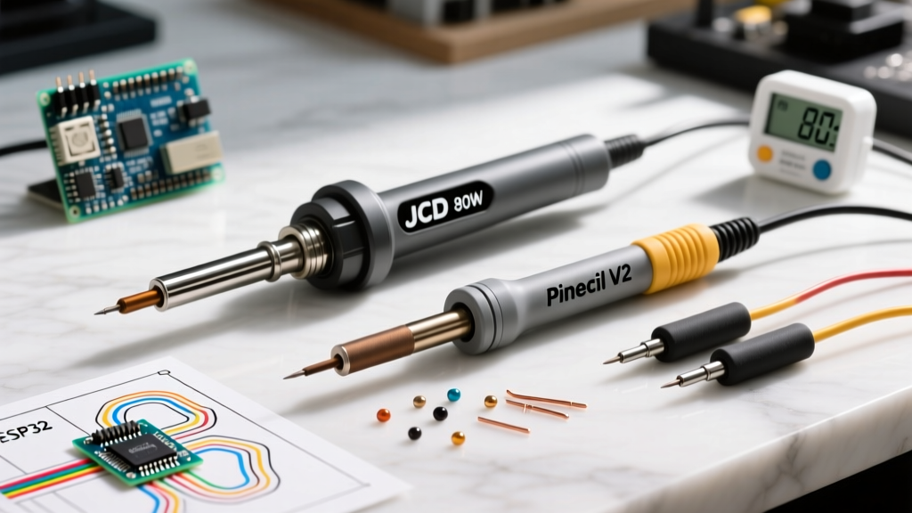
In an era where a highly capable smart iron like the Pinecil V2 costs under $30, you might wonder why anyone would ask how to make a soldering iron from scratch. The answer lies in education, emergency field repairs, and a fundamental understanding of thermal dynamics. Building your own iron forces you to confront the physics of Joule heating, thermal mass, and heat transfer efficiency—concepts that are abstract when you simply turn a dial on a commercial station.
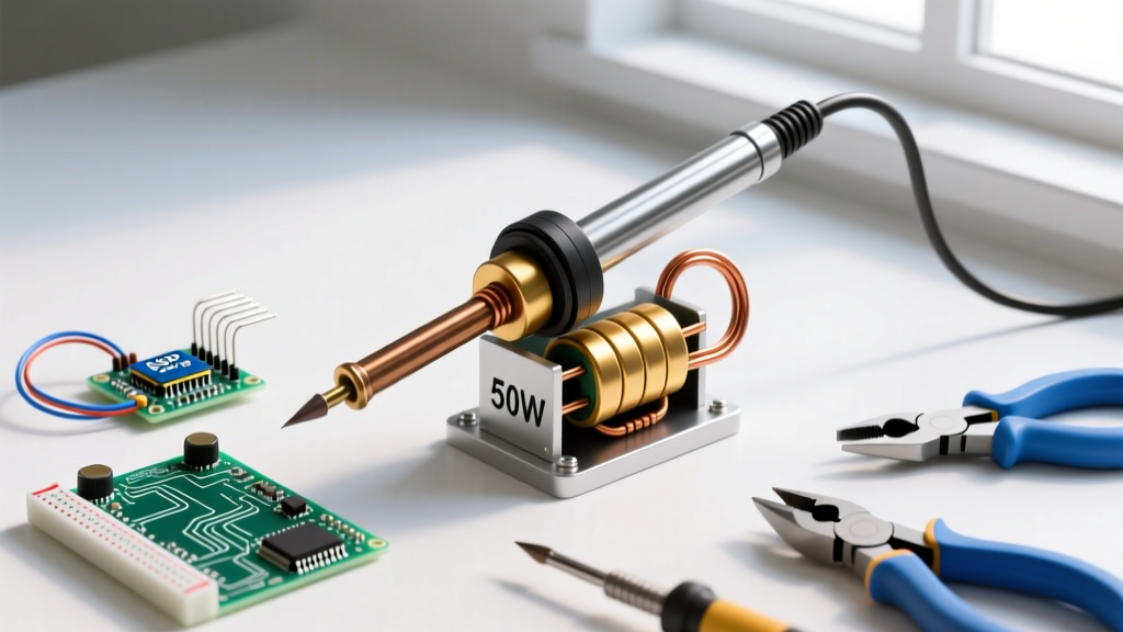
This beginner guide will walk you through constructing a safe, low-voltage DC soldering iron using a high-wattage aluminum-housed power resistor. We will cover the exact bill of materials, the math behind the heat generation, and the inevitable failure modes you must manage when using bare copper tips.
The Physics: Joule Heating and Thermal Equilibrium
At its core, a soldering iron is simply a controlled short circuit. When current flows through a resistive element, electrical energy is converted into heat. This is governed by Joule's First Law. As detailed in the foundational electronics curriculum at All About Circuits, power dissipation is calculated as:
P = V² / R
Where P is Power (Watts), V is Voltage (Volts), and R is Resistance (Ohms).
For our build, we will use a 12V DC power supply and a 5-Ohm resistor. This yields 28.8 Watts of continuous heat output. However, generating heat is only half the battle; transferring it to the solder joint is the real engineering challenge. Commercial irons use an iron-plated copper core to balance thermal conductivity with durability. Our DIY version will rely on mechanical clamping and bare copper, which introduces specific limitations we will address later.
Bill of Materials (BOM) and Tools
Sourcing the right components is critical for safety and performance. Do not substitute the aluminum-housed resistor with a standard ceramic wirewound resistor; the aluminum chassis acts as a vital thermal bridge and heat sink.
| Component | Specification / Part Number | Estimated Cost |
|---|---|---|
| Power Resistor | 50W 5-Ohm Aluminum Housed (e.g., Vishay RH0505R000FE02) | $8.50 |
| Soldering Tip | 12 AWG Solid Bare Copper Wire (approx. 2.05mm diameter) | $1.00 |
| Power Supply | 12V 5A DC Switching Supply (e.g., Mean Well LRS-60-12) | $18.00 |
| Handle Insulation | 1-inch Wooden Dowel + High-Temp Fiberglass Sleeving | $6.00 |
| Clamping Mechanism | Stainless Steel Hose Clamp (3/8" to 5/8" range) | $2.00 |
| Wiring | 16 AWG Silicone Stranded Wire (High Temp) | $7.00 |
Total Build Cost: ~$42.50
Step-by-Step Build Instructions
Step 1: Prepare the Copper Tip
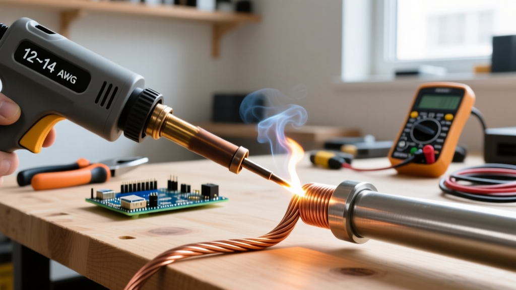
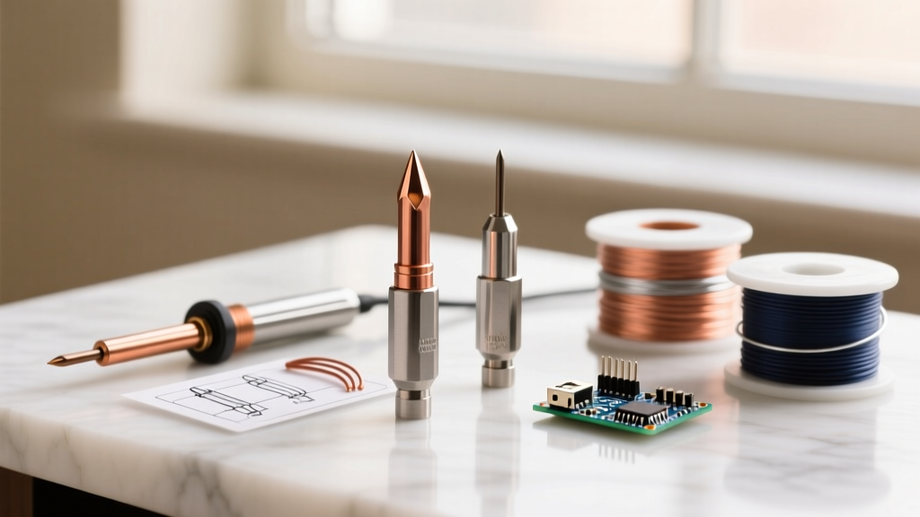
Cut a 4-inch length of 12 AWG solid copper wire. Using a metal file, shape one end into a 45-degree chisel point. The chisel shape maximizes surface area contact with the solder pad, reducing the thermal recovery time. Strip exactly 1.5 inches of insulation (if using coated wire) from the opposite end, which will interface with the resistor chassis.
Step 2: Machine the Thermal Interface
The flat surface of the Vishay aluminum resistor is your heating block. To ensure maximum thermal transfer, the 1.5-inch stripped section of your copper tip must sit perfectly flush against the aluminum housing. Use a flat file to flatten one side of the bare copper wire so it creates a mating surface with the resistor's flat side.
Expert Warning: Do not use standard CPU thermal paste (like Arctic MX-4) between the copper and the aluminum. At soldering temperatures (350°C+), the carrier oils in thermal pastes will vaporize, creating toxic smoke and leaving an insulating carbon crust that destroys heat transfer. Rely on bare, tight metal-to-metal contact.
Step 3: Clamp and Secure
Press the flattened copper wire against the side of the aluminum resistor. Secure it tightly using the stainless steel hose clamp. Tighten the clamp with a screwdriver until the copper cannot be moved by hand. Any micro-movements here will create an air gap, leading to catastrophic thermal lag.
Step 4: Wire the Power Leads
Solder your 16 AWG silicone wires directly to the terminal posts of the 50W resistor. Use high-temperature solder (like Sn96/Ag4, which melts at 221°C) for these connections so they do not desolder themselves from the ambient heat radiating off the resistor body.
Step 5: Assemble the Handle
Drill a 1/4-inch hole through the center of your 1-inch wooden dowel. Thread the silicone wires through the dowel. Slide the high-temp fiberglass sleeving over the wires and the back half of the resistor to protect the wood from scorching. Secure the dowel to the wires using a small amount of high-temp RTV silicone adhesive at the base.
Power Supply Selection and Safety Protocols
When learning how to make a soldering iron, safety is the most common point of failure for beginners. Never attempt to power a DIY iron directly from 120V/240V AC mains. A single insulation failure will route lethal current directly through the copper tip and into your hand.
Always use an isolated, UL-listed DC switching power supply. A 12V 5A brick provides 60W of headroom, ensuring the voltage doesn't sag when the cold copper tip hits a ground plane and draws maximum current. Furthermore, because you are working with bare copper and rosin fluxes, ensure your workspace is ventilated. The CDC's NIOSH guidelines on occupational lead exposure emphasize that rosin-based flux fumes combined with heavy metals require active extraction or adequate cross-ventilation to prevent respiratory sensitization.
DIY Resistor Iron vs. Modern Budget Stations
How does our 28.8W DIY creation stack up against modern entry-level commercial irons? Let's look at the data.
| Feature | DIY 50W Resistor Iron | Pinecil V2 (Smart Iron) | Hakko FX-601 (Ceramic) |
|---|---|---|---|
| Heating Element | External Aluminum Chassis | Internal Cartridge (T12 style) | Internal Ceramic Core |
| Wattage | ~28.8W (Fixed) | 65W (Dynamic) | 70W (Dynamic) |
| Temp Control | None (Thermal Equilibrium) | PID Algorithm (RISC-V) | Analog Dial Thermostat |
| Tip Lifespan | 10-15 Hours (Oxidation) | 100+ Hours (Iron Plated) | 200+ Hours (Iron Plated) |
| Best Use Case | Education, Emergency Field Fix | Daily Hobbyist / SMD Work | Heavy Through-Hole / Wires |
Troubleshooting Common Failure Modes
Because this DIY iron lacks active PID temperature control, you must manage its thermal state manually. Here are the edge cases you will encounter:
- Copper Tip Dissolution: Molten tin and activated rosin flux are highly corrosive to bare copper. Unlike commercial tips that feature an iron plating to resist this, your 12 AWG copper tip will slowly dissolve into the solder. Expect to re-file the chisel tip after every 10 to 15 hours of active soldering.
- Thermal Stall on Ground Planes: If you attempt to solder a capacitor to a multi-layer PCB with a heavy copper ground plane, the 28.8W output will be instantly absorbed. The iron will 'stall' and fail to melt the solder. Solution: Pre-heat the PCB with a hot air gun or a silicone heating mat to 100°C before applying the DIY iron.
- Oxidation Blackening: If left powered on without a layer of solder on the tip, the bare copper will oxidize black within minutes, completely rejecting new solder. Solution: Always leave a massive blob of sacrificial solder on the tip when setting the iron down, and wipe it on a damp brass sponge immediately before making a joint.
Conclusion: Knowing When to Upgrade
Learning how to make a soldering iron is a rite of passage for electronics enthusiasts. It demystifies the tool and teaches you to respect thermal mass and power budgets. However, once you move past basic through-hole components and begin working with 0805 SMD resistors or sensitive MOSFETs, the lack of precise temperature control and the rapid tip degradation of the DIY resistor iron will become a hindrance. Use this build to master the fundamentals, then reinvest your knowledge into a closed-loop cartridge station for your daily workbench.