
The Thermal Reality of 40W Soldering Irons
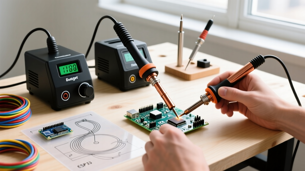
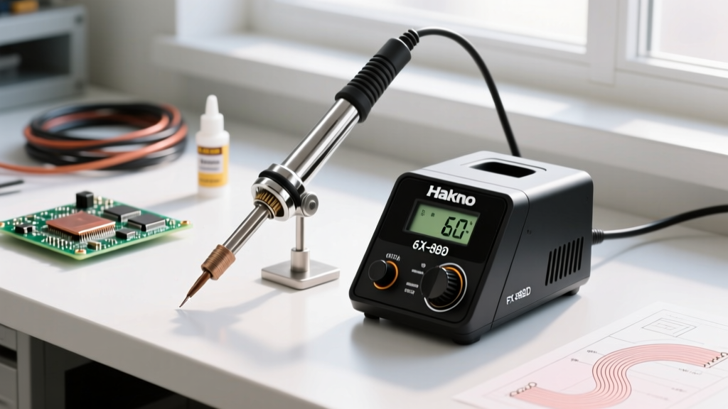
In the landscape of electronics repair and DIY prototyping, the 40W soldering iron occupies a unique middle ground. Models like the classic Weller SP40 or the Velleman VTSSC40N are ubiquitous on workbenches worldwide, typically priced between $25 and $55. However, managing the temperature of a 40W soldering iron requires a fundamentally different approach than using a $250 closed-loop station like the Hakko FX-951 or JBC CD-2BE. To master a 40W iron, you must understand the critical distinction between wattage (the rate of energy transfer) and temperature (the thermal state of the tip).
A standard 40W iron utilizes a basic resistive heating element, often regulated by a simple bimetallic strip or a manual triac dial. Unlike advanced stations that use an embedded thermocouple to pulse power and maintain a strict ±5°C tolerance, a 40W iron's temperature fluctuates wildly based on ambient thermal draw. As of 2026, while budget smart-irons have improved, the physical limitations of a 40W heating element remain a hard bottleneck. When you touch the tip to a massive copper ground plane, the iron cannot replenish the lost heat fast enough, leading to the dreaded 'thermal crash.' Understanding how to navigate this limitation is the hallmark of a true soldering expert.
Target Temperature Ranges by Solder Alloy
The ideal temperature of a 40W soldering iron is not a single fixed number; it is a dynamic target dictated by the metallurgical properties of your solder alloy. A common beginner mistake is cranking a dial-adjustable 40W iron to its maximum setting (often 450°C or higher) to 'force' the solder to melt. This instantly oxidizes the iron plating, ruins the flux core, and risks delaminating the PCB substrate.
Below is the definitive temperature matrix for the most common alloys used in modern electronics assembly:
| Solder Alloy | Composition | Melting Point | Target Tip Temp | Max Dwell Time |
|---|---|---|---|---|
| Leaded Eutectic | Sn63/Pb37 | 183°C (361°F) | 315°C - 350°C | 3 - 5 Seconds |
| Lead-Free (Standard) | SAC305 (Sn96.5/Ag3/Cu0.5) | 217°C (423°F) | 350°C - 380°C | 2 - 4 Seconds |
| Low-Temp Lead-Free | Sn42/Bi57.6 | 138°C (280°F) | 220°C - 250°C | 5 - 7 Seconds |
For general through-hole and 0805 SMD work using Sn63/Pb37, setting your adjustable 40W iron to roughly 330°C provides the perfect balance. The solder will wet the pad in under two seconds, well within the limits established by the NASA Workmanship Standards, which dictate strict dwell times to prevent thermal damage to component leads and internal PCB vias.
The 'Thermal Crash' and Ground Plane Survival
The greatest challenge when controlling the temperature of a 40W soldering iron is dealing with high-thermal-mass joints. When your 350°C chisel tip makes contact with a via connected to an internal ground plane on an FR-4 board, the copper acts as a massive heat sink. The tip temperature can plummet to 200°C in under a second.
Because the iron is capped at 40W of continuous energy transfer, it physically cannot replenish the lost heat as fast as a 70W or 90W station. If you hold the iron in place waiting for the solder to flow, you will exceed the maximum dwell time outlined in the IPC J-STD-001 requirements. Prolonged heat exposure causes the epoxy resin in the FR-4 to break down, leading to pad delamination, where the copper pad physically rips away from the fiberglass substrate.
Expert Workaround: Tip Geometry Over Dial Cranking
When faced with a thermal crash, amateurs turn the temperature dial up to 400°C+. Experts change the tip geometry. The physical shape of your tip dictates the surface area contact, which directly influences thermal transfer efficiency.
- Conical Tips (e.g., 1mm B-type): The absolute worst choice for a 40W iron. The microscopic contact area creates a high-resistance thermal bottleneck. The iron will stall on any joint larger than a 0603 resistor.
- Chisel Tips (e.g., 2.4mm or 3.2mm D-type): The optimal choice. A flat chisel tip increases the surface area contact by up to 400% compared to a conical tip. This allows the available 40W of energy to transfer into the joint rapidly, minimizing dwell time and preventing the core temperature of the iron from dropping.
- Bevel/Hoof Tips (e.g., 3mm C-type): Excellent for drag soldering SMD ICs, as the concave scoop holds a small reservoir of molten solder, maintaining localized thermal mass.
Step-by-Step Strategy for High-Mass Joints
If you must solder a heavy ground lug or a large capacitor using only a 40W iron, follow this precise sequence to compensate for the wattage limitation:
- Pre-Tin Both Surfaces: Apply liquid or gel flux to both the component lead and the PCB pad. Melt a small amount of solder onto the pad, and separately onto the component lead, creating a tinned layer on each.
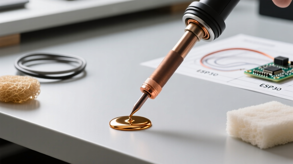
- Use a Thermal Bridge: Apply a generous blob of fresh, flux-cored solder to the tip of your 40W iron. This molten blob acts as a liquid thermal bridge, transferring heat from the iron to the joint infinitely faster than dry air or solid metal-to-metal contact.
- Apply and Count: Place the tinned tip against the pre-tinned joint. The existing solder on both surfaces will instantly alloy together. Count to three seconds, then remove the iron. As demonstrated in SparkFun's comprehensive soldering tutorials, a shiny, concave fillet indicates a perfect metallurgical bond.
- Cool Naturally: Never blow on the joint or move the component while the solder is in its plastic (semi-solid) phase. Disturbing a cooling joint results in a fractured, grainy 'cold joint' that will fail under vibration.
Failure Modes: When Temperature Mismanagement Ruins PCBs
The FR-4 Glass Transition Limit: Standard FR-4 PCB material has a Glass Transition Temperature (Tg) of roughly 130°C to 140°C. Above this point, the board transitions from a rigid state to a softened, pliable state. While the soldering iron tip is at 350°C, the localized heat dissipates through the board. If your dwell time exceeds 5-7 seconds on a 40W iron, the surrounding Tg threshold is breached for too long, causing micro-fractures in internal barrel plating and via separation.
Beyond board damage, mismanaging the temperature of a 40W soldering iron leads to rapid tip degradation. Modern soldering iron tips are not solid copper; they consist of a copper core plated with a thin layer of iron (to resist solder dissolution) and a chrome outer layer. If you leave a 40W iron idling at 400°C, the flux burns onto the iron plating, creating a black, crusty oxide layer. Once oxidized, the tip will not 'wet' with solder, effectively ruining a $10 replacement tip. Always dial your adjustable 40W iron down to 250°C or turn it off entirely if you are stepping away from the bench for more than five minutes.
Frequently Asked Questions
Can I use a 40W iron for modern lead-free (SAC305) manufacturing?
Yes, but with caveats. SAC305 requires a higher tip temperature (360°C - 380°C) to achieve proper wetting. A 40W iron can reach this temperature, but its thermal recovery will be sluggish. You must use a high-quality, no-clean flux (like Amtech NC-559 or Kester 951) to assist the wetting process, as the lower thermal mass of the 40W iron won't be able to rely on brute heat to burn through heavy oxidation on older lead-free pads.
My adjustable 40W iron dial has no numbers, just 'Min' and 'Max'. How do I set it?
Most generic 40W irons with a dial use a basic potentiometer. 'Min' usually equates to roughly 200°C, and 'Max' can exceed 480°C. For standard 63/37 leaded solder, set the dial to approximately the 11 o'clock position (about 60% of the maximum rotation). Test the iron by touching it to a piece of 63/37 solder wire; if it melts smoothly and wets the tip in 1.5 to 2 seconds without spitting flux violently, the temperature is in the optimal 320°C - 340°C range.
Why does my 40W iron melt solder fine, but fail on large connectors?
This is purely a wattage limitation. Large connectors (like barrel jacks, USB-A ports, or coaxial RF connectors) are physically anchored to large copper pours designed to absorb mechanical stress. These pours act as massive radiators. A 40W iron simply lacks the continuous joule-heating capacity to overcome the thermal dissipation rate of a 4-layer motherboard ground plane. For these specific joints, you must supplement your 40W iron with a bottom-side PCB pre-heater (set to 120°C) or a hot air rework station to elevate the ambient temperature of the board, reducing the thermal delta your 40W iron must overcome.