
The Architecture of Heavy-Duty Transformer Guns
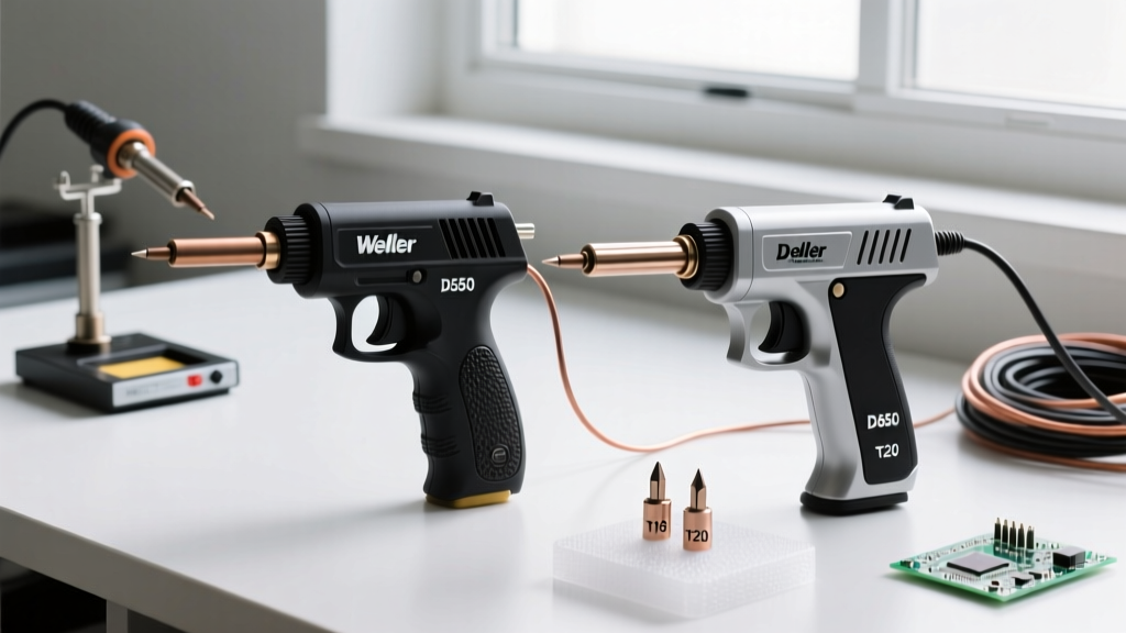
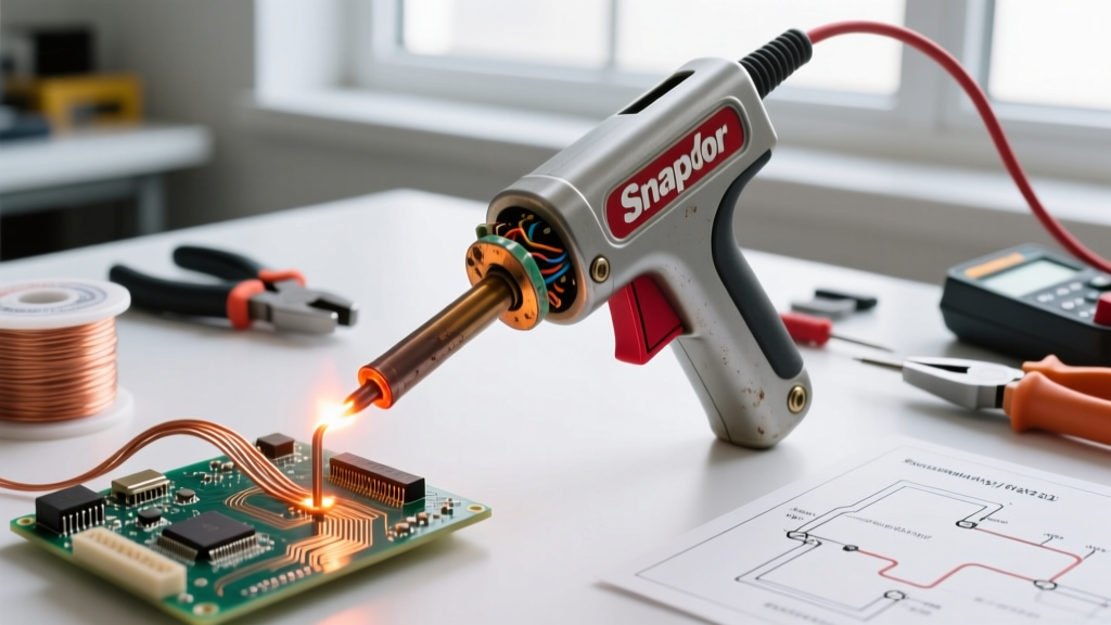
When working with heavy-gauge automotive wiring, thick ring terminals, or high-thermal-mass plumbing joints, standard ceramic-heater soldering stations fall short. This is where the Snap On soldering gun earns its keep. Models like the 100W CT1000 and legacy 150W transformer-based guns operate on a fundamentally different principle than modern digital stations. They utilize a massive step-down transformer to convert 120V AC mains voltage into a fraction of a volt (typically 0.5V to 1.5V AC) while pushing massive amperage (150 to 300 amps) through a heavy copper secondary loop.
As of 2026, while high-frequency induction soldering systems are gaining traction in professional bays, transformer guns remain ubiquitous due to their ruggedness and repairability. However, their high-current, low-voltage architecture introduces unique failure modes. Troubleshooting a Snap On soldering gun requires shifting your mindset from delicate electronics repair to heavy electrical diagnostics. Below, we detail the exact teardown, diagnostic, and repair procedures required to restore these tools to factory specifications.
Diagnostic Matrix: Isolating the Failure Point
Before opening the clamshell housing, use a digital multimeter (DMM) to categorize the failure. The table below maps common symptoms to their primary electrical suspects.
| Symptom | Primary Suspect | Multimeter Test | Corrective Action |
|---|---|---|---|
| Completely dead (no heat, no light) | Trigger switch or primary cord | Continuity test on cord; resistance on primary coil | Replace cord or microswitch |
| Intermittent heating / flickering | Pitted trigger contacts | Voltage drop across switch under load | Install higher-rated snap-action switch |
| Low heat / slow melting | Secondary loop oxidation | Milliohm reading across loop joints | Disassemble, wire-brush, and re-torque |
| Tip sparking / arcing at base | Loose terminal screws | Visual inspection for heat warping | Clean threads, apply conductive grease, tighten |
| Humming noise, tip stays cool | Shorted secondary loop | Visual check for loop touching housing | Re-bend copper loop for clearance |
Phase 1: Trigger Switch and Primary Circuit Repair
The primary side of a Snap On soldering gun operates at standard line voltage (120V AC). The most frequent point of failure here is the trigger microswitch. When you pull the trigger, you are engaging a circuit that feeds the primary winding of the transformer. Because transformers are highly inductive loads, breaking the circuit when you release the trigger generates a voltage spike (inductive kickback). Over thousands of cycles, this spike causes micro-arcing across the internal contacts of the switch, leading to pitting, carbon buildup, and eventual voltage drop.
Testing and Replacing the Microswitch
- Safety First: Unplug the gun. Never work on the primary circuit while energized.
- Teardown: Remove the perimeter screws on the heat-resistant thermoplastic housing. Carefully separate the halves, noting the placement of the strain relief bushing and trigger spring.
- Continuity Check: Set your DMM to the resistance (Ω) setting. Place probes on the switch terminals. Pull the trigger. A healthy switch will read near 0.00Ω. If the reading fluctuates or stays above 1.0Ω, the contacts are pitted.
- The Upgrade Fix: Do not simply replace the switch with an identical cheap OEM part. Upgrade to a heavy-duty snap-action microswitch (such as the Honeywell V15 series or Cherry E22 series) rated for at least 15A at 125V AC with a high inrush tolerance. This single upgrade will eliminate intermittent trigger failures for the lifespan of the tool.
Inspecting the Primary Coil
If the switch tests fine but the gun remains dead, test the primary coil. Disconnect the coil leads from the switch and cord. Set your DMM to the 200Ω range. A healthy 100W primary coil should read between 12Ω and 20Ω. If you read infinite resistance (OL), the internal thermal fuse has blown, or the fine copper wire inside the winding has fractured due to thermal expansion cycles. In this scenario, the transformer must be replaced or professionally rewound.
Phase 2: Secondary Loop Degradation and Micro-Arcing
The secondary loop is the business end of the Snap On soldering gun. It consists of a thick copper tube or braided strap that connects to the transformer's secondary winding via brass terminal blocks. This loop carries upwards of 250 amps. At this amperage, even a microscopic layer of cupric oxide (corrosion) acts as a massive resistor.
The Skin Effect and Contact Resistance
Because the secondary current is alternating (AC at 50/60Hz), it travels primarily on the outer surface of the copper conductor—a phenomenon known as the skin effect. If the surface of the copper loop where it mates with the brass terminal block is oxidized, the current is forced through a restricted cross-section. This generates intense localized heat (I²R losses) at the joint, melting the surrounding plastic housing and starving the soldering tip of the current it needs to reach 400°C.
Restoring the Secondary Connection
- Remove the two heavy screws securing the copper loop to the transformer terminals.
- Use a brass wire brush or a fiberglass scratch pen to aggressively clean the mating surfaces of both the copper loop and the brass block until they are bright and shiny. Never use a steel file or sandpaper, as embedded ferrous metals will accelerate galvanic corrosion.
- Apply a microscopic amount of electrical contact grease (such as Noalox or standard dielectric grease) to prevent future oxidation without impeding conductivity.
- Reinstall the screws. Torque them firmly (approximately 15-20 in-lbs). The heat cycles of the gun will naturally loosen these screws over time; checking this torque is a mandatory bi-annual maintenance step.
The AC Pitting Phenomenon: Advanced Tip Maintenance
Users frequently complain that the tips on transformer soldering guns degrade and pit much faster than those on DC-powered ceramic stations. This is not a defect; it is a byproduct of AC physics.
Expert Insight: The alternating current passing through the tip creates a microscopic electrolytic effect at the boundary between the copper core and the iron plating, especially when flux residues are present. This accelerates localized oxidation and pitting. To combat this, you must maintain a continuous barrier of molten solder on the tip when the gun is active.
To maximize tip life on a Snap On soldering gun, adhere to the following protocol:
- Never dry-fire the gun. Do not pull the trigger unless the tip is already coated in solder or actively touching a soldered joint.
- Use high-rosin flux. When cleaning the tip, use a damp cellulose sponge or brass wool, then immediately apply a thick layer of 60/40 or 63/37 rosin-core solder to seal the iron plating from atmospheric oxygen.
- Avoid mechanical shock. Transformer gun tips are secured by a single set screw. Tapping the gun against a workbench to knock off slag can misalign the internal copper core, causing the tip to heat unevenly and burn out prematurely.
Preventative Maintenance Protocol for 2026 and Beyond
To ensure your Snap On soldering gun remains reliable for heavy-duty electrical and plumbing tasks, implement this structured maintenance schedule:
- Daily: Wipe down the housing with a silicone cloth to remove acidic flux vapors. Inspect the power cord for cuts or brittle insulation near the strain relief.
- Monthly: Check the tip set-screw for tightness. Re-tin the tip heavily before storing the tool.
- Bi-Annually: Open the housing. Inspect the secondary loop terminal screws and re-torque. Check the primary wiring for any signs of heat discoloration near the trigger switch.
- Annually: Test the ground continuity (if equipped with a 3-prong plug) and verify the trigger switch voltage drop under load.
Safety and Compliance Standards
Working with high-current soldering tools requires strict adherence to safety protocols. According to the OSHA Hand and Power Tools guidelines, all electrical hand tools must be inspected for grounding integrity and cord damage before each use. Furthermore, when using these guns for critical electrical connections (such as automotive battery cables or industrial control panels), your workmanship should align with the IPC J-STD-001 soldering standards, which dictate proper wetting, fillet formation, and thermal management to ensure the mechanical and electrical integrity of the joint. A poorly maintained gun that fluctuates in temperature will result in cold, crystalline solder joints that will inevitably fail under vibration or thermal cycling.
By understanding the transformer architecture and respecting the high-amperage secondary loop, you can keep your Snap On soldering gun operating at peak performance, turning a potential frustration into your most reliable heavy-duty shop tool.