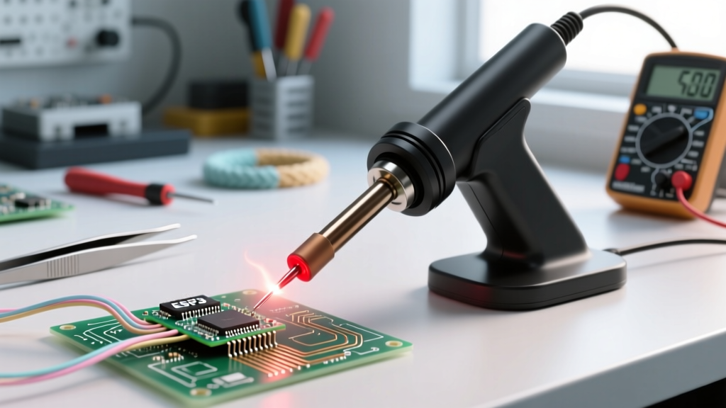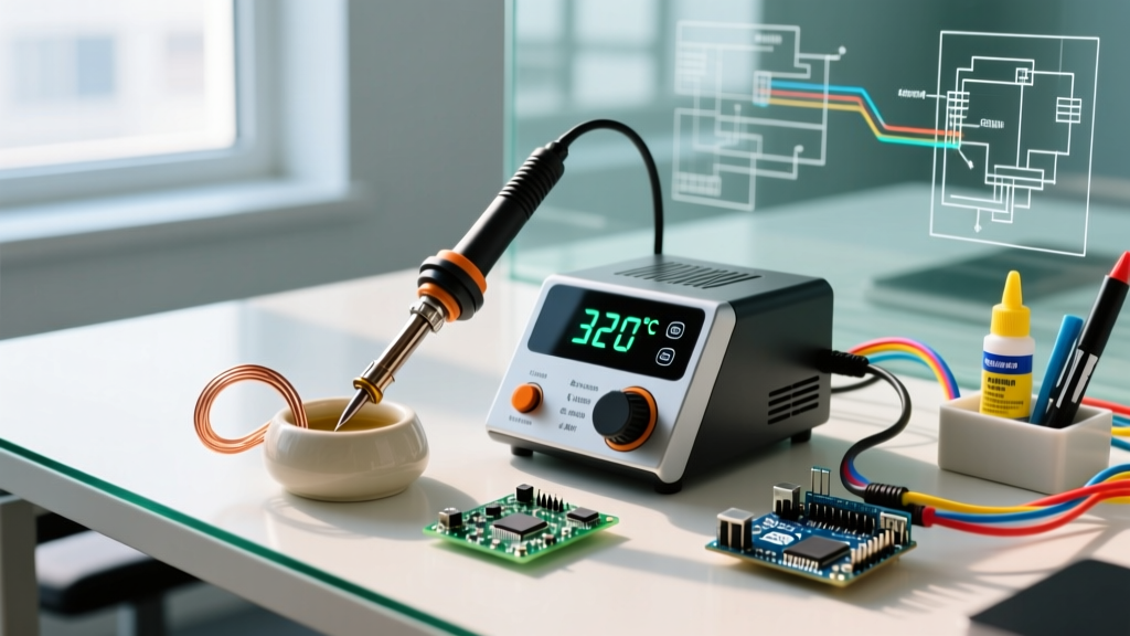

The Three Faces of Soldering Iron Burn
When electronics engineers, technicians, and DIYers mention a soldering iron burn, they are usually referring to one of three distinct failures: physical skin burns from poor ergonomic setup, thermal damage (burns) to the PCB and sensitive components, or severe oxidation burns on the iron's tip. While physical safety is paramount, thermal mismanagement is the silent killer of electronics projects. Cranking your station to 400°C to 'melt solder faster' is a fundamental misunderstanding of thermodynamics that guarantees pad delamination, destroyed silicon, and rapid tip degradation.
In this comprehensive setup and calibration tutorial, we will explore the exact thermal parameters required to eliminate soldering iron burns across your workspace, your boards, and your equipment. Whether you are using a budget-friendly Pinecil V2 or a professional Weller WE1010NA, precise temperature control is your first line of defense.
The Thermodynamics of Tip Burn and PCB Damage
To prevent a soldering iron burn on your PCB, you must understand the relationship between thermal mass and temperature. Soldering is about transferring a specific amount of thermal energy (Joules) to a joint in a controlled timeframe.
- PCB Substrate Limits: Standard FR4 material has a Glass Transition Temperature (Tg) between 130°C and 170°C. High-Tg boards can withstand up to 180°C. When localized heat exceeds these thresholds for more than 3 to 5 seconds, the epoxy resin expands faster than the copper cladding, resulting in pad lifting and trace delamination.
- Component Limits: Most surface-mount ICs and plastic-bodied connectors begin to suffer internal die-attach degradation at sustained temperatures above 260°C.
- Tip Oxidation (Tip Burn): According to Hakko's official technical guidelines, iron plating on soldering tips oxidizes rapidly when left idle above 350°C. This black crust acts as a thermal insulator. When an oxidized tip fails to transfer heat, the operator inevitably increases the temperature and applies physical pressure, crushing the joint and burning the board.
Step-by-Step Calibration for Thermal Safety
Factory calibration on modern stations is generally accurate to within ±5°C, but environmental factors, power supply voltage drops (especially with USB-C PD triggers on portable irons), and tip seating can introduce drift. Here is how to calibrate your station to ensure your dial matches reality.
Required Tools
- Digital Multimeter with a K-type thermocouple probe.
- High-temperature Kapton tape.
- Thermal interface paste (optional, but improves surface contact accuracy).
The Calibration Procedure
- Secure the Probe: Bend the K-type thermocouple bead flat against the very tip of your soldering iron (e.g., a Hakko T18-D or Weller RT series). Secure it tightly with two layers of Kapton tape.
- Set the Baseline: Turn on your station (e.g., Pinecil V2 or FX-888D) and set the target temperature to 320°C. Allow it to stabilize for 3 full minutes.
- Read and Compare: Check the multimeter reading. If the station reads 320°C but the multimeter reads 312°C, you have an 8°C negative offset.
- Apply the Offset: On smart irons like the Pinecil V2, navigate to the 'Settings' menu and adjust the 'Calibration Offset' value. On analog or digitally adjusted stations like the Weller WE1010NA, use the front-panel pushbuttons to apply the delta.
- Verify at Extremes: Repeat the test at 250°C (for low-temp solders) and 380°C (for heavy ground planes) to ensure linear accuracy across the operational spectrum.
Temperature Matrix: Matching Heat to Solder Alloy
The most common cause of a soldering iron burn on a PCB is using a one-size-fits-all temperature setting. Lead-free alloys require significantly more thermal energy than traditional leaded solders. Use the matrix below to set your baseline temperatures and strictly enforce maximum dwell times.
| Solder Alloy | Melting Point | Ideal Iron Temp | Max Dwell Time |
|---|---|---|---|
| Sn63/Pb37 (Leaded) | 183°C | 300°C - 320°C | 3 Seconds |
| , Copper;'>SAC305 (Lead-Free) | 217°C - 220°C | 330°C - 350°C | 4 Seconds |
| Sn42/Bi57 (Low Temp) | 138°C | 220°C - 250°C | 2 Seconds |
Tip Maintenance: The Wet Sponge vs. Brass Wool Debate
How you clean your tip during a session directly impacts your risk of causing a soldering iron burn on the board. The traditional wet cellulose sponge is a thermal shock hazard. When a 350°C tip touches a wet sponge, the temperature plummets by up to 100°C in a fraction of a second. This rapid thermal cycling causes micro-fractures in the iron plating, leading to pitting and core corrosion.
Furthermore, because the tip loses so much heat, the heater element goes into overdrive to recover, often overshooting the target temperature momentarily. When you immediately touch the board after cleaning on a wet sponge, that thermal overshoot can instantly burn delicate SMD pads.
Best Practice: Switch to a dry brass wire sponge (like the Hakko 599B). Brass shavings clean oxidation and excess flux without dropping the tip temperature, ensuring thermal stability and drastically reducing the chance of PCB thermal shock.
Diagnostic Guide: Is It a Burn or Just Flux?
Beginners often mistake burnt flux residue for a soldering iron burn on the PCB substrate. Here is how to tell the difference:
- Burnt Flux: Dark brown or amber, sticky or glassy, and can be removed with 99% Isopropyl Alcohol (IPA) and a stiff brush. The underlying fiberglass and copper remain intact.
- Thermal PCB Burn: The FR4 substrate appears charred black, gray, or whitish. The surface feels rough or delaminated. IPA will not remove it. The structural integrity of the board is compromised.
User Safety: Preventing Physical Soldering Iron Burns
While protecting your PCB is critical, protecting your skin is non-negotiable. A standard 65W iron operating at 350°C will cause third-degree burns in less than a second of contact. According to Cornell University's Environmental Health and Safety (EHS) soldering protocols, proper workspace geometry is the most effective way to prevent physical burns.
Ergonomic Setup Rules
- The Holster Rule: Never rely on the cheap, stamped-metal stands included with budget irons. Invest in a heavy, weighted silicone-matted holder. The iron should sit at a 45-degree angle, with the handle extending toward your dominant hand, ensuring you never reach over the hot barrel.
- Cable Management: Use a boom arm or a simple overhead bungee cord to suspend the silicone power cable. This prevents the cable from snagging on the desk edge and pulling the 350°C iron into your lap or across your arm.
- Fume Extraction: Thermal burns aren't the only hazard; colophony-based flux fumes are severe respiratory sensitizers. Position an activated carbon fume extractor (like the Hakko FA-400) within 6 inches of the solder joint to capture particulates before they reach your face.
Summary: The Calibration Mindset
Preventing a soldering iron burn is not about buying the most expensive station; it is about respecting the thermodynamics of the materials you are joining. By calibrating your equipment with a K-type thermocouple, matching your temperature to the specific alloy's melting point, utilizing high-thermal-mass tips, and abandoning the wet sponge, you will achieve flawless, shiny fillets without ever scorching a PCB or destroying a silicon die. Treat your temperature dial as a precise scientific instrument, not a volume knob, and your yield rate will reflect the discipline.