
The Anatomy of a Precision Repair Bench
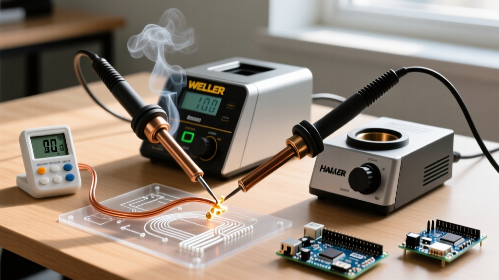
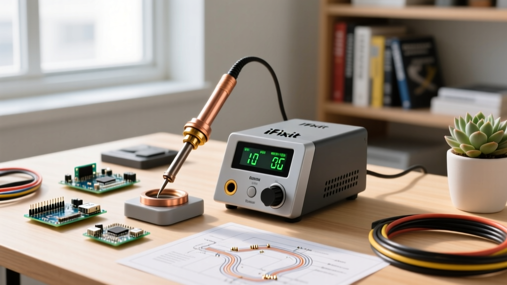
Setting up an iFixit soldering station goes far beyond simply plugging in the iron and melting wire. Whether you are using the classic iFixit Soldering Workstation (historically built around the Hakko FX-888D architecture) or their modern 60W USB-C Smart Soldering Iron bundle, precise thermal management is the dividing line between a reliable micro-soldering joint and a catastrophically lifted BGA pad. As of 2026, modern PCBs feature dense ground planes and highly heat-sensitive SMD components that demand exact temperature control.
This comprehensive setup and calibration tutorial will walk you through environmental preparation, thermal stabilization, and the exact offset calibration protocol required to ensure your iFixit station reads true to the tip.
Phase 1: Environmental and Physical Setup
Before applying power, your physical workspace must be optimized for both safety and electrostatic discharge (ESD) protection. The iFixit Soldering Workstation includes a high-temperature silicone mat, but proper placement is critical.
Bench Layout and Fume Extraction
Rosin-based flux fumes (colophony) are a known respiratory sensitizer. According to the CDC NIOSH guidelines on soldering, localized exhaust ventilation is mandatory to prevent occupational asthma. Position your fume extractor's intake nozzle exactly 6 to 8 inches away from the soldering zone, angled slightly behind the workpiece so the plume is pulled away from your breathing zone without disrupting the iron's thermal envelope.
ESD Mat Grounding
If your iFixit bundle includes an ESD-safe silicone mat, ensure it is properly grounded. Use a 1-megohm resistor grounding cord connected to a verified earth ground. The ESD Association fundamentals dictate that a 1-megohm resistor is required to safely dissipate static charges without creating a shock hazard if you accidentally touch a live circuit while grounded.
Phase 2: The Science of Thermal Transfer and Tip Selection
The iFixit station's temperature dial or digital readout measures the internal ceramic heating element, not the absolute tip surface. Thermal degradation occurs across the air gap and the physical mating surface between the heater and the tip. This is why factory calibration is rarely perfect for your specific ambient room temperature and chosen tip geometry.
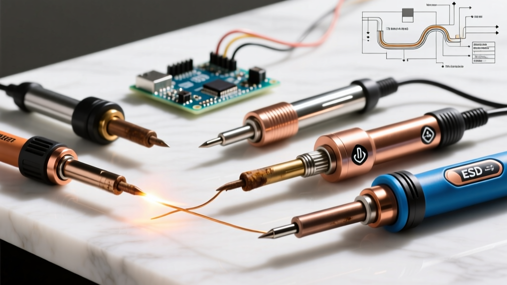
- Conical Tips (e.g., iFixit 0.4mm): Ideal for 0402 SMD components. High thermal resistance; requires higher base station offsets to maintain 320°C at the point.
- Chisel Tips (e.g., 2.4mm D-Chisel): Best for through-hole and general wire tinning. Excellent thermal mass transfer.
- Hoof/Knife Tips: Essential for drag-soldering QFP ICs and clearing solder bridges on dense connector pins.
Pro-Tip: Never use a wet cellulose sponge to clean your iFixit iron tip. The rapid thermal contraction from 350°C to 100°C causes micro-fractures in the tip's iron plating, leading to rapid oxidation and copper core dissolution. Always use the dry brass wool sponge included in the iFixit Workstation.
Phase 3: Step-by-Step Temperature Calibration Protocol
To calibrate your iFixit soldering station, you need a K-type thermocouple tip thermometer (such as the Hakko FG-100B or a generic equivalent with a surface-contact sensor). Do not rely on infrared thermometers; they cannot accurately read the emissivity of polished metal tips and will yield errors of up to 40°C.
Calibration Steps
- Initial Stabilization: Power on the iFixit station and set the target temperature to 320°C (608°F). Allow the iron to idle in its holder for exactly 3 minutes to reach full thermal equilibrium.
- Prep the Sensor: Apply a small amount of fresh, high-quality flux to the thermocouple's K-type sensor pad.
- Create a Thermal Bridge: Melt a tiny bead of eutectic Sn63/Pb37 solder onto the very tip of your iFixit iron. This liquid solder bridge is mandatory; without it, air gaps will cause the thermocouple to read 20°C to 50°C lower than reality.
- Measure: Press the thermocouple sensor firmly but gently into the molten solder bead on the tip. Hold for 5 seconds until the reading stabilizes.
- Record and Adjust: Note the delta between the station's display and the thermocouple. Access the station's calibration menu (on digital smart irons, this is via the OLED menu; on analog workstation bases, use the provided flathead screwdriver to adjust the internal offset potentiometer under the front panel cap).
Calibration Data Matrix
Use this reference table to verify your offsets based on standard leaded solder profiles.
| Station Target | Thermocouple Reading | Delta (Offset) | Required Action |
|---|---|---|---|
| 320°C (608°F) | 305°C (581°F) | -15°C | Increase internal offset by +15°C |
| 320°C (608°F) | 322°C (611°F) | +2°C | No adjustment needed (within ±3°C tolerance) |
| 320°C (608°F) | 338°C (638°F) | +18°C | Decrease internal offset by -18°C |
Phase 4: Setting Profiles for Modern Electronics
Once your station is calibrated to read true at the tip, you must select the correct operating temperature for your specific solder alloy. Using excessive heat to compensate for poor thermal transfer will destroy the PTFE heater core over time and delaminate internal PCB vias.
Leaded vs. Lead-Free Alloys
- Sn63/Pb37 (Eutectic Leaded): Melts at 183°C. Set your calibrated iFixit station to 315°C - 325°C. This provides the optimal 130°C superheat required for rapid wetting without burning the rosin flux core.
- SAC305 (Lead-Free): Melts at 217°C. Set your station to 350°C - 360°C. Lead-free alloys have a higher surface tension and require more aggressive flux activation. If you are soldering large ground planes with SAC305, do not exceed 380°C; instead, use an iFixit silicone pre-heater mat set to 80°C underneath the board to reduce the thermal gradient.
Phase 5: Troubleshooting Edge Cases and Failure Modes
Even with perfect calibration, environmental factors and maintenance habits can cause your iFixit soldering station to underperform. Consult this troubleshooting matrix before assuming the heating element has failed.
Failure Mode: "Black Tip" Oxidation Syndrome
Symptom: Solder balls up and rolls off the tip; the tip appears black or dark blue.
Root Cause: Leaving the iron at 380°C+ while idle, or using cheap solder with low flux content, burns the protective iron plating, exposing the copper core to rapid oxidation.
Fix: Turn the station off immediately. Once cool, use a specialized tip tinner (a mixture of aggressive acid flux and solder powder). Heat the iron to 250°C, plunge it into the tip tinner, and wipe on brass wool. Never sand an oxidized tip; you will destroy it instantly.
Failure Mode: Intermittent Heating / Error Codes
Symptom: The iFixit station display flashes an error (e.g., "Sensor Open" or flashing temperature digits), and the tip goes cold.
Root Cause: The K-type thermocouple sensor inside the ceramic heater has fractured, or the mating pins between the handle and the station base are coated in oxidized flux residue.
Fix: Unplug the station. Inspect the 5-pin DIN connector (or USB-C data pins on smart irons). Clean with 99% isopropyl alcohol and a fiberglass scratch pen. If the error persists, the heater core's internal thermocouple wire has snapped from mechanical drop shock, requiring an $8-$12 replacement heater element.
Final Thoughts on Maintenance
Proper setup of your iFixit soldering station is an ongoing process. For the most comprehensive visual guide on basic joint formation and maintenance, always refer back to the foundational iFixit How to Solder Guide. By strictly adhering to thermocouple calibration, utilizing dry brass wool, and respecting the thermal limits of your specific solder alloy, your iFixit workstation will deliver factory-grade reliability for years of micro-soldering and heavy-duty wire work alike.