
The Direct Answer: What Is the Temperature of a Soldering Iron?
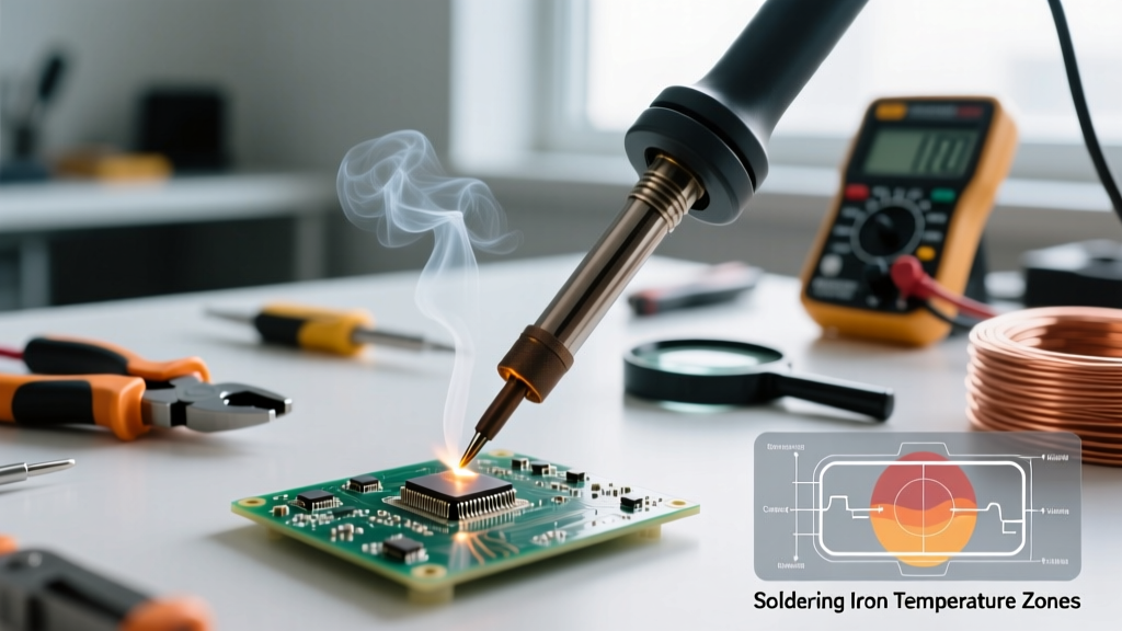
When beginners ask, 'what is the temperature of a soldering iron,' they are usually looking for a single magic number. The reality of thermal dynamics in electronics manufacturing is more nuanced. For general printed circuit board (PCB) work, the ideal soldering iron tip temperature sits between 300°C and 350°C (570°F to 660°F). However, this baseline shifts dramatically depending on the solder alloy's melting point, the thermal mass of the components, and the wattage of your station.
The Golden Rule of Soldering: The dial on your soldering station does not dictate the temperature of the solder joint; it dictates the thermal recovery ceiling of the tip. Your goal is to achieve a dwell time of 1.5 to 3 seconds per joint, minimizing thermal stress on the PCB substrate.
According to the IPC (Association Connecting Electronics Industries) J-STD-001 standards, the focus is not strictly on the iron's dial temperature, but on the actual wetting time and the thermal profile of the joint. Pushing your iron to 450°C to melt solder faster is a common misconception that leads to catastrophic pad delamination and rapid tip oxidation.
Solder Alloy Melting Points vs. Tip Temperatures
To set your station correctly, you must first understand the metallurgy of your consumables. The tip must be significantly hotter than the alloy's liquidus point to transfer heat rapidly through the flux and into the copper pad.
- Leaded Solder (Sn63/Pb37): Melts at 183°C (361°F). This eutectic alloy transitions instantly from solid to liquid. Ideal tip temperature: 300°C - 320°C.
- Lead-Free Solder (SAC305): Melts at 217°C (423°F). Requires higher thermal energy to overcome the surface tension of the tin-silver-copper matrix. Ideal tip temperature: 330°C - 360°C.
- High-Temp / Plumbing Alloys (95/5 Tin-Copper): Melts around 227°C - 250°C. Used for copper pipes and heavy grounding lugs. Ideal tip temperature: 400°C - 450°C (requires high-wattage irons).
Application-Specific Temperature Matrix
Use the following matrix as a starting point for your station dial. Always adjust based on the visual behavior of the flux and the wetting speed.
| Application Scenario | Recommended Alloy | Target Tip Temperature | Max Dwell Time |
|---|---|---|---|
| Standard Through-Hole (THD) | Sn63/Pb37 | 310°C (590°F) | 2.0 - 3.0 seconds |
| SMD 0805 / 0603 Passives | SAC305 | 340°C (645°F) | 1.0 - 1.5 seconds |
| Heavy Ground Planes / Multilayer | Sn63/Pb37 | 380°C (715°F) | 3.0 - 5.0 seconds |
| Heat-Sensitive ICs / Flex PCBs | Low-Temp (BiSn) | 240°C (465°F) | 1.0 - 2.0 seconds |
| Copper Plumbing (1/2 inch) | 95/5 Tin-Copper | 420°C (788°F) | Continuous until wet |
The Thermal Mass Illusion: Why Dial Temperature Lies
Understanding thermal recovery is what separates hobbyists from professionals. If you are using a budget 60W iron like the popular Pinecil V2 ($26), the digital display might read 350°C. But the moment you touch a large copper ground plane, the tip temperature can plummet to 180°C in milliseconds. The microcontroller will pulse power to recover, but the joint remains cold, resulting in a grainy, disturbed solder joint.
Conversely, a professional cartridge-based system like the JBC CD-2BE ($450) utilizes a 130W transformer and an integrated tip-cartridge where the heating element is millimeters from the contact point. When the JBC C245 cartridge touches that same ground plane, it maintains 350°C continuously.
Station Tier Comparison: Thermal Recovery Capabilities
- Entry-Level (e.g., Hakko FX-888D, $105): 70W ceramic heater. Excellent for standard SMD and THD. Struggles with 4-layer PCB ground planes unless you increase tip mass (e.g., switching from a conical B-tip to a bevel C4 tip).
- Mid-Range (e.g., Weller WE1010NA, $115): 70W with highly stable PID control. Maintains +/- 5°C accuracy in idle and standard load states.
- Professional (e.g., JBC CD-2BE, $450): 130W cartridge system. Instantaneous thermal recovery. Allows you to run the dial lower (e.g., 320°C) while achieving faster wetting than a cheap iron set to 400°C, vastly extending tip life and preventing PCB scorching.
Failure Modes: The Cost of Incorrect Heat
The NASA Electronic Parts and Packaging (NEPP) Program workmanship manuals heavily emphasize the visual inspection of thermal damage. Setting your iron to the wrong temperature triggers specific, often irreversible, failure modes.
1. Running Too Hot (>400°C for standard electronics)
- Flux Burn-Off: The rosin or synthetic flux vaporizes before the solder can wet the pad, leaving a black, oxidized residue that prevents adhesion.
- Tip Oxidation: Iron plating on the tip degrades exponentially above 400°C. A $15 replacement tip can be ruined in a single weekend of high-heat misuse.
- Pad Lifting: The FR-4 fiberglass substrate utilizes epoxy resins that soften around 260°C. Prolonged exposure to a 420°C tip will delaminate the copper trace from the board.
2. Running Too Cold (<280°C for lead-free)
- Cold Solder Joints: The solder forms a high-contact-angle ball (beading) rather than flowing into a concave fillet. These joints are mechanically brittle and prone to micro-cracking under thermal cycling.
- Ironic Heat Damage: Because the iron is too cold, the operator holds it against the pad for 8+ seconds waiting for the solder to flow. This prolonged, low-grade heat transfer soaks into the IC package, potentially damaging internal silicon dies or melting plastic connector housings.
Step-by-Step: Calibrating Your Station for Precision
Do not blindly trust the digital readout on your station. Over time, thermocouple drift and heater degradation can cause a 20°C variance between the display and the actual tip. Here is how to verify your temperature using a tip thermometer (such as the Hakko 191 or 191-215).
- Clean and Tin: Thoroughly clean the tip on a brass wire sponge and apply a fresh coat of your working solder to ensure maximum thermal transfer to the sensor.
- Set the Baseline: Set your station dial to 330°C (626°F) and allow it to idle for 3 minutes to reach thermal equilibrium.
- Apply Sensor Paste: Place a small dab of thermal transfer paste (usually included with the thermometer) on the sensor pad. This eliminates air gaps that cause false low readings.
- Measure: Press the tinned tip squarely onto the sensor pad with moderate, consistent pressure (about the weight of the iron itself). Wait 3 seconds for the reading to stabilize.
- Offset Calibration: If the thermometer reads 315°C, access your station's hidden calibration menu (refer to your manual, e.g., holding the 'UP' button on the Hakko USA FX-888D while powering on) and apply a +15°C offset.
Final Technique Advice: Match the Tip, Not Just the Temp
If you find yourself constantly raising the temperature to get solder to flow on large pads, you are using the wrong tip geometry. A fine-point conical tip has terrible thermal mass. Switch to a bevel (C-shape) or chisel (D-shape) tip that matches the width of the pad. A massive chisel tip set to 320°C will transfer heat infinitely faster and safer than a needle tip cranked to 400°C. Mastering what the temperature of a soldering iron should be is ultimately about balancing alloy chemistry, tip geometry, and thermal recovery.