
The Thermodynamics of Soldering: Beyond "Melting Metal"
When electronics engineers and hobbyists ask, "how do you use a soldering iron," they are frequently met with oversimplified advice: touch the iron to the joint and apply solder. However, precision PCB rework and through-hole assembly are exercises in applied thermodynamics and fluid dynamics. To achieve reliable, IPC-compliant joints, you must manage thermal mass, understand intermetallic compound (IMC) formation, and master flux chemistry.
According to SparkFun's comprehensive soldering guide, the most common beginner mistake is using the soldering iron as a delivery tool for molten solder. This is fundamentally incorrect. The iron's sole purpose is to transfer thermal energy to the copper pad and component lead simultaneously. The solder must be melted by the joint itself, ensuring the flux has properly activated and the surfaces are ready for capillary wetting.
Step-by-Step: Executing the Perfect Through-Hole Joint
Mastering the physical technique requires a strict adherence to timing and geometry. The entire soldering event for a standard through-hole component on 1.6mm FR-4 material should take between 1.5 and 3.0 seconds.
- Preparation and Tinning: Clean your tip using a dry brass wire sponge. Avoid wet cellulose sponges; the rapid thermal shock causes micro-fractures in the tip's iron plating, leading to premature pitting and corrosion. Apply a microscopic layer of fresh solder to the tip to create a thermal bridge.
- Flux Activation: Apply a high-quality Rosin Mildly Activated (RMA) or No-Clean flux (e.g., Kester 245) to the joint. As noted in Adafruit's Guide to Excellent Soldering, flux is a chemical oxygen barrier. It dissolves copper oxides at 150°C and prevents re-oxidation as temperatures climb.
- The Heat Transfer Phase: Place the flat surface of a chisel tip against both the PCB pad and the component lead. Hold for exactly 1 second to allow the thermal mass of the joint to reach the solder's liquidus temperature.
- The Feed Phase: Introduce your solder wire (0.8mm diameter is optimal for standard through-hole) to the opposite side of the joint, away from the iron tip. Capillary action will draw the molten alloy through the plated through-hole (PTH).
- The Withdrawal Phase: Remove the solder wire first, wait 0.5 seconds for the flux to fully volatize, and then sweep the iron away at a 45-degree angle to create a smooth, concave fillet.
Tip Geometry Selection Matrix
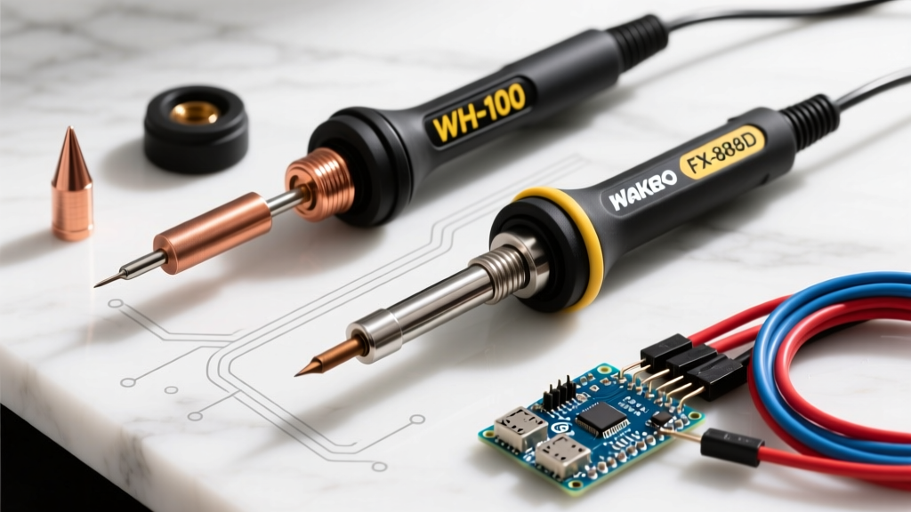
Selecting the correct tip geometry is just as critical as temperature control. A conical tip concentrates heat into a tiny point, which is disastrous for large ground planes that act as thermal heat sinks. Conversely, a massive chisel tip will bridge fine-pitch SMD pads. Below is a decision matrix for 2026's most common rework scenarios:
| Tip Geometry | Model Example | Best Application | Thermal Transfer Rate |
|---|---|---|---|
| Chisel (Standard) | Hakko T18-D24 | Through-hole, heavy ground planes, wire tinning | High |
| Conical (Pointed) | Weller ETA | Fine-pitch SMD (0603/0402), tight clearance areas | Low |
| Hoof / Mini-Wave | JBC C115-112 | Drag soldering QFP ICs, SMD connector pins | Medium-High |
| Knife (K-Type) | Pine64 Pinecil K-Tip | Edge soldering, scraping oxidation, drag soldering | Medium |
Temperature Profiling for Modern Solder Alloys
Understanding the liquidus and solidus temperatures of your alloy dictates your station setpoint. In 2026, while lead-free mandates dominate commercial manufacturing, hobbyists and specialized aerospace rework still heavily utilize eutectic leaded alloys for their superior wetting characteristics and lower thermal stress on components.
Expert Insight: Never set your station to the exact melting point of the alloy. You must account for the thermal delta required to overcome the heat sink effect of the PCB copper layers and the component's internal thermal mass.
- Sn63/Pb37 (Eutectic Leaded): Melts at exactly 183°C. Station setpoint: 320°C to 350°C. Ideal for DIY, vintage electronics restoration, and quick rework.
- SAC305 (Lead-Free): Melts at 217°C (with a pasty range). Station setpoint: 350°C to 380°C. Requires higher thermal capacity irons and aggressive flux formulations to prevent cold joints.
- Sn42/Bi57 (Low-Temp Bismuth): Melts at 138°C. Station setpoint: 220°C to 250°C. Used exclusively for heat-sensitive components and step-soldering processes. Warning: Bismuth joints are highly brittle and fail under mechanical shear stress.
Diagnosing and Preventing Critical Failure Modes
Even experienced technicians encounter metallurgical defects. Recognizing these failure modes is the final step in answering how do you use a soldering iron effectively. For deeper troubleshooting, resources like CircuitBasics' soldering tutorials provide excellent visual references for these defects.
1. The Cold Joint
Visual Signature: Dull, grainy, or lumpy appearance with a high contact angle (poor wetting).
Root Cause: Insufficient heat transfer to the pad, movement during the solidification phase, or oxidized solder wire. The intermetallic compound (IMC) layer fails to form properly, resulting in a high-resistance mechanical bond that will crack under thermal cycling.
2. Pad Delamination
Visual Signature: The copper pad lifts away from the FR-4 fiberglass substrate, often taking the plated through-hole barrel with it.
Root Cause: Exceeding a 3-second dwell time with an iron set above 380°C. The epoxy resin in the PCB reaches its glass transition temperature (Tg) and loses structural integrity. Fix: Use a pre-heater board to bring the ambient PCB temperature to 100°C before applying localized iron heat.
3. Flux Burnout and Char
Visual Signature: Black, crusty, carbonized residue surrounding the joint that is highly corrosive.
Root Cause: Iron temperature exceeds 400°C, or the iron is held on the joint for more than 5 seconds. The rosin activators break down into corrosive salts. Always clean with 99% isopropyl alcohol (IPA) and a lint-free swab if using non-no-clean fluxes.
Active-Tip Technology and 2026 Maintenance Protocols
Modern soldering stations have evolved past traditional ceramic heating elements. In 2026, active-tip systems like the JBC CD-2BE (retailing around $450) and Metcal PS-900 dominate professional benches. These stations embed the thermocouple and heating element directly inside the tip cartridge, achieving thermal recovery in under 0.5 seconds.
However, this extreme responsiveness requires strict maintenance protocols. Leaving an active tip in a holder at 380°C will cause rapid oxidation of the iron plating, rendering the tip unwettable in a matter of hours. Always configure your station's auto-sleep feature to drop the temperature to 150°C after 5 minutes of inactivity. Furthermore, never apply excessive mechanical pressure; let the thermal conductivity do the work. Pressing harder does not transfer heat faster—it merely crushes the microscopic iron plating, exposing the copper core to rapid dissolution by the molten tin.
Final Thoughts on Precision Rework
Learning how to use a soldering iron is not about memorizing a single motion; it is about developing a tactile understanding of thermal gradients and fluid wetting. By selecting the correct tip geometry, respecting the activation temperatures of your flux, and strictly managing your dwell time, you will consistently produce bright, concave, and structurally sound solder joints that meet the highest IPC workmanship standards.