
The Core Question: How Hot Should a Soldering Iron Be?
When setting up a new workstation, the most common question beginners ask is, "how hot should soldering iron be?" The instinct for many is to crank the temperature dial to the maximum setting to ensure the solder melts instantly. In 2026, with advanced lead-free alloys and densely packed multilayer PCBs, this approach is a guaranteed way to destroy your soldering tips, lift copper pads, and create brittle intermetallic joints.
The correct temperature is not a single universal number. It is a dynamic balance between the solder alloy's melting point, the thermal mass of the components, and the geometry of your soldering tip. The iron's tip must be hot enough to transfer sufficient thermal energy to the pad and lead within 1 to 3 seconds, but cool enough to prevent the flux from vaporizing before it can clean the oxidation. According to the IPC Association Connecting Electronics Industries, excessive dwell times and temperatures lead to thermal degradation of both the PCB substrate and the component's internal die.
Temperature Matrix by Solder Alloy
To determine the baseline temperature for your station, you must first identify your solder alloy. The iron temperature should generally be set 60°C to 140°C above the alloy's liquidus (melting) point to account for thermal loss upon contact with the board.
| Solder Alloy | Composition | Melting Point | Ideal Iron Temp | Target Dwell Time |
|---|---|---|---|---|
| Sn63/Pb37 | 63% Tin, 37% Lead | 183°C (361°F) | 280°C - 320°C | 1 - 2 seconds |
| SAC305 | 96.5% Sn, 3% Ag, 0.5% Cu | 217°C (423°F) | 320°C - 360°C | 2 - 3 seconds |
| Sn95/Sb5 | 95% Tin, 5% Antimony | 235°C (455°F) | 340°C - 380°C | 2 - 4 seconds |
| Sn42/Bi58 | 42% Tin, 58% Bismuth | 138°C (280°F) | 220°C - 250°C | 1 - 2 seconds |
Note: If you are working with large ground planes or heavy connectors (like USB-C or XT60 battery plugs), you will need to increase the temperature by 20°C to 30°C to compensate for the massive thermal drain, or switch to a higher-wattage station.
The Physics of Thermal Transfer: Why Tip Mass Matters
Understanding how hot a soldering iron should be requires understanding thermal transfer. A common mistake is using a microscopic conical tip (e.g., Hakko B-2 or Pinecil TS-C1) for large pads. Because the conical tip has very little thermal mass, it loses its heat the millisecond it touches a copper ground plane. The user then compensates by raising the station temperature to 420°C, which rapidly oxidizes the tip's iron plating.
Expert Rule of Thumb: Never increase the temperature to solve a thermal transfer problem. Increase the tip surface area. A wide chisel tip (e.g., Hakko D-24 or Weller RT4) at 340°C will solder a heavy ground pin faster and cleaner than a conical tip at 400°C.
For standard 0805 and 0603 surface-mount components, a 320°C setting with a 1.2mm chisel tip is optimal. For through-hole components with standard thermal relief pads, 340°C with a 2.4mm chisel tip provides the perfect balance of speed and safety.
Step-by-Step Calibration for Popular 2026 Stations
Even high-end stations suffer from thermal drift. The temperature sensor is located inside the heating element, not at the very tip of the iron. This creates a thermal gradient. Calibrating your station ensures the digital readout matches the actual temperature at the tip's working surface.
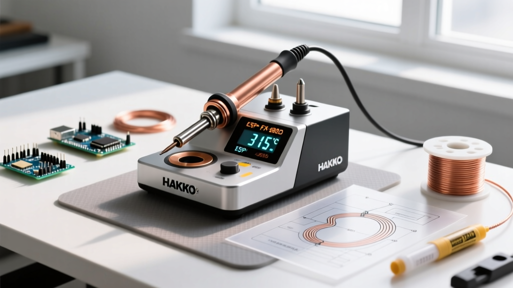
Calibrating the Hakko FX-888D Digital Station
The Hakko FX-888D (retailing around $115 in 2026) is an industry staple, but it requires manual offset calibration.
- Preparation: Install a fresh T18 tip and allow the station to idle at 350°C for at least 5 minutes to reach thermal equilibrium.
- Measurement: Use a dedicated tip thermometer (such as the Hakko FG-100B, approx. $135) with a fresh K-type thermocouple sensor. Press the sensor firmly against the flat face of the tip.
- Enter Calibration Mode: Turn the station off. Press and hold the UP arrow button, then turn the station back on. The display will show the current offset value.
- Adjust Offset: Use the UP and DOWN arrows to adjust the offset until the digital display matches the reading on your tip thermometer. Press ENTER to save.
Calibrating the Pinecil V2 (IronOS Firmware)
The open-source Pinecil V2 (approx. $28) running IronOS offers highly granular software calibration.
- Boot the Pinecil V2 into the main menu by holding the 'A' button while plugging in your USB-C power source.
- Navigate to Settings > Calibration.
- IronOS will prompt you to input the current ambient room temperature (use a standard room thermometer for accuracy).
- Next, it will heat the tip and ask for the boiling point of water. Boil a cup of distilled water, hold the tip in the steam (not the liquid), and input the exact boiling point based on your current altitude.
- The firmware automatically calculates the ADC (Analog-to-Digital Converter) curve offset, resulting in lab-grade temperature accuracy.
Troubleshooting Thermal Failures
If your joints are not meeting the visual requirements of the NASA Electronic Parts and Packaging (NEPP) Program workmanship standards, your temperature setup is likely flawed. Here is how to diagnose the failure modes:
- Cold Joints (Grainy, dull, lumpy appearance): The temperature is too low, the tip is too small, or the dwell time was too short. The flux burned off before the solder could wet the copper. Fix: Increase tip size or raise temperature by 20°C.
- Scorched Pads and Lifted Traces: The temperature is excessively high (above 380°C for standard FR4), or the iron was held on the pad for more than 4 seconds. The epoxy resin in the PCB is breaking down. Fix: Lower temperature, use a larger tip to reduce dwell time, and apply fresh liquid flux.
- Rapid Tip Oxidation (Blue/Yellow crust): The iron is being left at 350°C+ while idle. Fix: Always use your station's sleep mode, or manually drop the temperature to 200°C when not actively soldering. Never leave a tip bare; always coat it in a thick layer of solder before putting it in the holder.
Industry Standards and Best Practices
Professional electronics manufacturing relies on strict thermal profiles. When setting up your station, always refer to established guidelines rather than guesswork. The Adafruit Excellent Soldering Guide and IPC-A-610 standards both emphasize that the goal is to heat the joint, not just melt the solder. The solder wire should be fed to the pad and component lead, not melted directly on the iron tip and dragged to the joint, which starves the connection of flux and creates a weak mechanical bond.
By understanding the specific thermal requirements of your solder alloy and matching your tip geometry to the component's thermal mass, you will achieve consistent, shiny, and structurally sound solder joints every time.