
The Critical Interface: Why Your Weller Soldering Iron Tip Dictates Joint Quality
When electronics engineers and advanced hobbyists invest in a high-end soldering station, they often obsess over the wattage of the base unit or the responsiveness of the PID controller. However, the true bottleneck in any soldering process is the physical interface between the heating element and the solder joint: the tip. Selecting the correct Weller soldering iron tip is not merely a matter of physical fit; it is a complex exercise in thermal dynamics, metallurgy, and geometry. A mismatched tip will result in cold joints, lifted pads, or component damage, regardless of whether you are using a legacy WES51 or a modern WX2 station. This guide provides an expert-level breakdown of the Weller tip ecosystem, focusing on the metallurgical construction, series distinctions, and thermal mass paradoxes that dictate professional rework outcomes in 2026.
Anatomy of a Weller Tip: Beyond the Copper Core
To understand why specific Weller tips excel in different scenarios, you must understand their layered construction. A genuine Weller tip is not a simple piece of metal; it is a precision-engineered thermal conduit consisting of four distinct layers:
- Tellurium Copper Core: The heart of the tip is a high-purity copper alloy (often doped with tellurium for machinability). Copper provides the rapid thermal conductivity required to pull heat from the wand's ceramic heater and push it into the solder joint.
- Iron Plating: Molten solder, particularly lead-free alloys like SAC305, aggressively dissolves raw copper. To prevent the tip from eroding, Weller electroplates the working end with a precise layer of iron. The thickness of this iron layer (measured in microns) dictates the tip's lifespan and its thermal transfer efficiency.
- Chrome Plating: The non-working areas of the tip are chrome-plated to prevent solder from wicking up the shaft, which would cause bridging and make tip changes dangerous.
- Wetting Area: The very apex of the tip features a specialized tin-iron alloy coating that allows molten solder to adhere, creating the thermal bridge to the PCB pad.
Decoding the Weller Ecosystem: ET vs. LT vs. RT Series
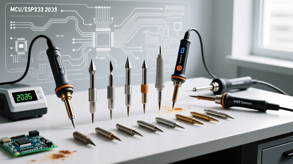
Weller's modern and legacy lineup is divided into three primary tip families. Confusing these series is a common error, as they are mechanically and electrically incompatible. Below is the definitive matrix for identifying and selecting the right series for your station.
| Series | Compatible Stations & Wands | Connection Type | Integrated Heater? | Max Wattage | 2026 Avg Price |
|---|---|---|---|---|---|
| ET Series | WES51, WESD51 (Legacy PES51 wand) | Screw-on Collar | No (Heater in wand) | 50W | $8 - $12 |
| LT Series | WSP80, WXP80 (WX1, WX2 stations) | Slip-on Retaining Nut | No (Heater in wand) | 80W | $10 - $14 |
| RT Series | WXP120, WX2020 (WX1, WX2 stations) | Direct Plug-in | Yes (Active Tip) | 40W | $15 - $19 |
The RT Series Active Tip Advantage
The RT series represents a paradigm shift in micro-soldering. Unlike the ET and LT series, where the temperature sensor and heating element reside inside the wand handle, the RT series integrates the heater and thermocouple directly into the base of the tip itself. This drastically reduces the thermal lag between the sensor and the working end, allowing the WX station to compensate for heat loss in milliseconds. According to the Weller Tools Knowledge Base, this active tip technology is what allows a 40W RT tip to outperform older 80W passive tips when soldering dense, multi-layer PCBs.
The Thermal Mass Paradox: Selecting Tip Geometry
A pervasive myth in DIY electronics is that smaller components require smaller, needle-like tips. This misunderstanding of thermal mass leads to catastrophic rework failures, particularly when dealing with ground planes.
SMD Components (0402, 0603, and QFPs)
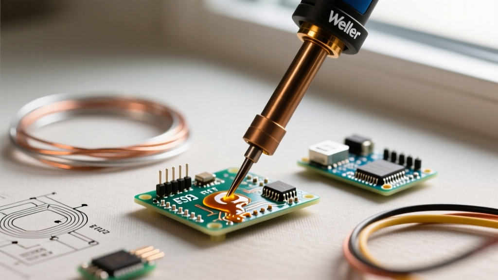
When soldering a 0402 capacitor to a standard signal trace, a micro-conical tip (like the RTW1) seems logical. However, if that same pad is connected to an internal ground plane via a thermal relief via, the PCB will act as a massive heat sink. A needle tip lacks the thermal mass to overcome this sink. The tip temperature will plummet upon contact, and the station will aggressively overdrive the heater, potentially scorching the pad.
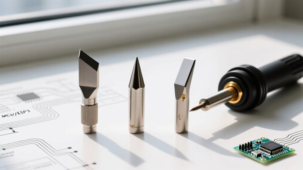
Expert Rule: For SMD components on multi-layer boards, always default to a chisel or bevel geometry (e.g., RT1 or LT1). The flat surface area maximizes thermal transfer, allowing you to use a lower station temperature (330°C) while achieving rapid wetting. The physical width of a 1.6mm chisel tip is still narrow enough to bridge 0.5mm pitch QFP leads without shorting them, provided you use drag-soldering techniques with ample flux.
Heavy Through-Hole and TO-220 Packages
For large through-hole connectors or power components like TO-220 voltage regulators, the LT series (80W) with a heavy screwdriver or large bevel tip (e.g., LTA or LT7) is mandatory. The goal is to match the tip's thermal mass to the combined mass of the component lead and the barrel of the plated through-hole (PTH). The NASA Workmanship Standards for Soldering dictate that a proper PTH joint requires the solder to wick completely through the barrel, achieving a minimum 270-degree wetting angle. This is physically impossible if the tip geometry cannot simultaneously contact the lead and the inner barrel wall to transfer sufficient joules of heat.
Lead-Free Soldering (SAC305): Temperature and Dwell Time Strategies
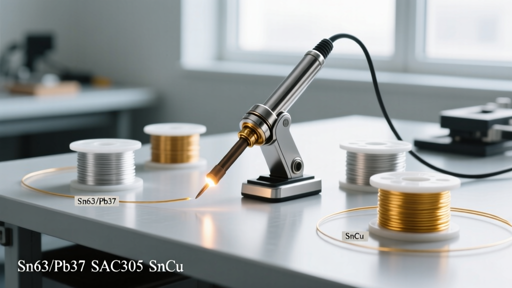
The transition to RoHS-compliant lead-free solders, primarily SAC305 (Tin/Silver/Copper), has fundamentally altered tip selection and temperature profiling. SAC305 has a melting point of 217°C, roughly 34°C higher than traditional Sn63/Pb37 eutectic solder. Furthermore, its surface tension is higher, resulting in poor wetting characteristics.
Expert Profiling Guideline: When using Weller LT or RT tips with SAC305, set your station to 350°C - 370°C. Do not exceed 380°C. While higher temperatures seem like they would compensate for the higher melting point, temperatures above 380°C exponentially accelerate the dissolution of the tip's iron plating, reducing tip lifespan by up to 60%. Instead of raising the temperature, increase the thermal mass of the tip (use a wider chisel) to maintain dwell times under 3 seconds per joint, as recommended by the IPC J-STD-001 Standard.
Troubleshooting Failure Modes: Pitting, Blackening, and Non-Wetting
Even premium Weller tips will fail prematurely if subjected to improper maintenance. Recognizing the specific failure mode is critical for diagnosing your process errors.
- Pitting (Irreversible): If you see small craters or rough spots on the wetting area, the iron plating has been breached, exposing the copper core. The flux and molten tin are now actively dissolving the copper. Action: The tip is dead. Discard it immediately. Pitting is caused by using excessively high temperatures, leaving the iron on for hours without use, or using abrasive cleaners.
- Blackening / Oxidation (Reversible): A dark, crusty layer forms on the tip, preventing solder from wetting. This is iron oxide and carbonized flux residue. Action: Do not scrape it. Use a damp cellulose sponge or brass wire wool to gently wipe the tip at operating temperature, followed immediately by an application of fresh rosin-core solder to re-tin the surface.
- Non-Wetting / De-wetting (Reversible): Solder balls up and falls off the tip instead of coating it. This often occurs when the tip is exposed to air at high temperatures without a protective solder coating. Action: Use a commercial tip activator paste (such as Amtech BC-1 or Weller's proprietary tip cleaner). Dip the hot tip into the paste, wipe on brass wool, and immediately apply fresh solder.
Expert Maintenance Protocols for Maximum Tip Lifespan
To maximize the ROI on your Weller soldering iron tips (which can cost upwards of $60-$100 a year for active production benches), implement the following standard operating procedures:
- Never Use Tap Water: When using a cellulose sponge, wet it only with distilled water. Tap water contains calcium and magnesium minerals that will bake onto the hot tip, creating an insulating layer of scale that ruins thermal transfer.
- Embrace Brass Wool: Damp sponges cause a rapid thermal shock every time you wipe the tip, micro-fracturing the iron plating over time. Dry brass wire wool (never steel wool, which will scratch the iron) is the superior cleaning method as it removes oxidation without dropping the tip temperature.
- The Solder Shield: Always leave a massive blob of solder on the tip before powering down the station. This sacrificial layer will oxidize and absorb atmospheric moisture while the iron is off, protecting the delicate iron plating underneath. Simply wipe it off upon powering up the next day.
- Right-Size the Temperature: Modern WX stations feature a 'Standby' or 'Sleep' mode that drops the tip temperature to 150°C when the wand is placed in the cradle. Ensure this feature is enabled. Running an RT or LT tip at 360°C continuously, even when not actively soldering, will destroy the iron plating via oxidation within a matter of weeks.
By treating your Weller soldering iron tip as a precision thermal instrument rather than a disposable consumable, you will achieve IPC-compliant joints, reduce component stress, and drastically lower your annual bench supply costs.