
The Myth of 'One Temperature Fits All'
Ask a novice what temp for soldering iron they use, and they will likely quote a single, static number—usually around 350°C (662°F)—regardless of the task. Ask a senior PCB assembly engineer, and you will get a nuanced answer involving thermal mass, alloy composition, and tip geometry. Finding the optimal temperature is not about melting solder; it is about achieving thermal equilibrium between the iron tip, the component lead, and the copper pad within a precise dwell time window.
Cranking your station to 400°C to 'heat things faster' is a fast track to lifted pads, oxidized tips, and brittle intermetallic joints. Conversely, running too cold causes incomplete wetting and grainy cold joints. In this expert guide, we break down the exact temperature profiles required for modern electronics assembly in 2026, referencing industry benchmarks like the IPC J-STD-001 standard for soldered electrical assemblies.
The Alloy Baseline: Melting Points vs. Working Temperatures
Your baseline temperature is dictated by the solder alloy's liquidus (melting) point. The general rule of thumb for manual soldering is to set your station 40°C to 80°C above the alloy's melting point. However, the exact offset depends entirely on the thermal mass of the joint.
- Sn63/Pb37 (Leaded Eutectic): Melts at 183°C. Ideal working range: 240°C to 280°C.
- SAC305 (Lead-Free Standard): Melts at 217°C–220°C. Ideal working range: 280°C to 340°C.
- Sn96.5/Ag3.0/Cu0.5 (High-Reliability Lead-Free): Melts at 217°C. Requires aggressive thermal delivery due to poor wetting characteristics compared to SAC305.
- Sn42/Bi57.5 (Low-Temp Bismuth): Melts at 138°C. Ideal working range: 180°C to 210°C. Used for step-soldering or heat-sensitive RF modules.
Expert Insight: Never use a high-temperature lead-free profile (350°C+) on a board that has already undergone a reflow cycle with low-temperature Bismuth solder. The localized heat will melt underlying structural joints, causing catastrophic component shifting.
Expert Temperature Matrix by Component Type
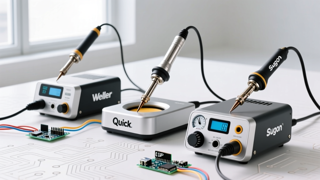
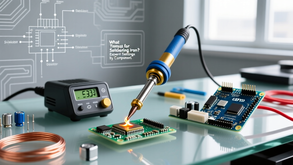
The following matrix assumes the use of a modern, active-tip soldering station (such as a JBC CD-2BQE or a high-end Weller WE1010NA) with appropriately sized tips. Dwell time should never exceed 3 seconds for standard SMD or 5 seconds for heavy through-hole joints.
| Application / Joint Type | Recommended Alloy | Target Station Temp | Max Dwell Time | Optimal Tip Geometry |
|---|---|---|---|---|
| 0402 / 0603 SMD Passives | Sn63/Pb37 or SAC305 | 280°C – 300°C | 1.5 – 2.0 sec | Micro-Conical (e.g., JBC C245-116) |
| SOIC / QFP IC Leads | SAC305 | 300°C – 320°C | 1.0 sec / pin | Micro-Chisel (1.5mm width) |
| Standard Through-Hole (DIP) | Sn63/Pb37 | 300°C – 320°C | 2.0 – 3.0 sec | Standard Chisel (2.4mm width) |
| Heavy Ground Planes / TO-247 | SAC305 or Sn96.5 | 340°C – 360°C | 4.0 – 5.0 sec | Heavy Bevel / Spoon (5mm+ width) |
| Heat-Sensitive Connectors | Sn42/Bi57.5 | 190°C – 210°C | 2.0 sec | Knife or Mini-Wave |
Thermal Mass and Station Architecture: Why 320°C isn't Always 320°C
When determining the right temp for soldering iron tasks, you must understand your station's sensor architecture. A budget $40 station with a ceramic heater and a separate thermocouple will suffer from massive thermal lag. When you touch a large ground plane, the tip temperature plummets, and the heater overshoots aggressively to compensate, often frying the component once the heat finally catches up.
Active Cartridge Systems vs. Passive Tips
In 2026, professional labs rely on active cartridge systems where the heating element, sensor, and tip are a single integrated unit. For example, a NASA-approved soldering setup often utilizes JBC or Pace ADS200 stations. Because the thermocouple is located millimeters from the tip apex, the station detects a 2°C drop and injects 130 watts of power instantly. Therefore, an expert using a JBC station can solder a heavy ground plane at 330°C, while a user with a passive Hakko FX-888D might need to crank their dial to 380°C to achieve the exact same thermal transfer—increasing the risk of localized scorching.
Failure Modes: What Happens When You Guess the Temp
Guessing your temperature settings leads to distinct, diagnosable failure modes. Understanding these will help you reverse-engineer whether your temp for soldering iron is too high or too low.
1. The 'Too Hot' Failures
- Flux Burn-Off and Oxidation: Modern no-clean fluxes (ROL0/ROL1 classifications) are designed to activate between 150°C and 220°C. If your tip is at 400°C, the flux vaporizes instantly upon contact before it can remove oxides from the copper pad, resulting in a balling effect where the solder refuses to wet.
- IMC Overgrowth: Soldering creates an Intermetallic Compound (IMC) layer (typically Cu6Sn5) between the solder and the copper pad. While a thin IMC layer is necessary for a metallurgical bond, excessive heat and dwell times cause this layer to grow too thick. A thick IMC layer is highly brittle and will crack under mechanical stress or thermal cycling.
- FR4 Delamination: Standard FR4 PCB material has a Glass Transition Temperature (Tg) around 135°C. High-Tg boards sit around 170°C. Prolonged exposure to 380°C+ causes the epoxy resin to break down, leading to pad lifting, mealing, and internal via barrel cracking.
2. The 'Too Cold' Failures
- Cold Joints: Characterized by a dull, grainy, or lumpy appearance. This occurs when the solder cools before the flux has fully cleaned the surface, or when the joint is disturbed during the plastic (semi-solid) phase of cooling.
- Incomplete Hole Fill: In plated through-hole (PTH) components, insufficient heat prevents the solder from wicking up the barrel via capillary action. According to expert soldering guidelines, a Class 3 IPC joint requires a minimum of 75% barrel fill, which is impossible without adequate preheating of the entire barrel mass.
Pro-Tips for Advanced Thermal Management
Beyond the dial on your station, experts use physical techniques to manipulate the effective temperature delivered to the joint.
The Tip Geometry Multiplier
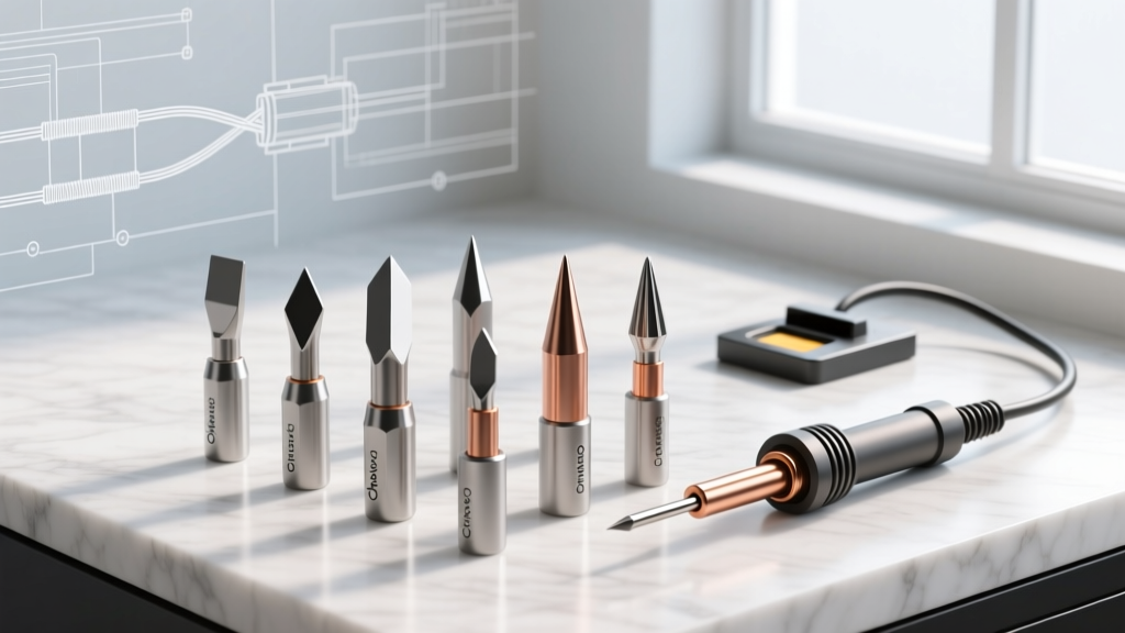
Never use a conical tip for heavy work. A conical tip has a microscopic surface area contact point with a flat PCB pad, resulting in terrible thermal transfer regardless of how high you set the temperature. Switching to a chisel or bevel tip increases the contact area by 400%, allowing you to drop your station temperature by 30°C while achieving faster, safer heat transfer. Match the tip width to the pad size; the tip should never overflow the pad boundaries.
Preheating the Board
When working on multi-layer boards with internal copper pours (which act as massive heat sinks), do not compensate by maxing out your iron. Instead, use a PCB preheater (like a Quick 853A or an Aoyue hot air bed) to bring the ambient board temperature up to 100°C–120°C. This reduces the thermal delta between the iron and the board, allowing you to use a lower, safer iron temp (e.g., 300°C instead of 360°C) while maintaining a perfect 2-second dwell time.
Wet Sponge vs. Brass Wool
How you clean your tip radically affects its working temperature. Wiping a 350°C tip on a damp cellulose sponge causes a violent thermal shock, dropping the tip apex temperature by up to 50°C momentarily. If you immediately apply it to a joint, you will get a cold joint. Conversely, using a dry brass wool tip cleaner only drops the temperature by roughly 10°C–15°C, maintaining your thermal equilibrium and vastly extending the lifespan of your tip's iron plating.
Final Calibration Advice
The correct temp for soldering iron work is a dynamic variable, not a static setting. Start at the lower end of the recommended matrix for your specific alloy. If the solder does not flow and wet the pad within 2 seconds, increase the temperature in 10°C increments. Never jump straight to maximum heat. By respecting the thermal limits of your components and leveraging the correct tip geometry, you will produce IPC-compliant, high-reliability joints every time.