
The Core Question: Beyond Basic Resistance
When makers and technicians ask, how does a soldering iron work?, the elementary answer is straightforward: electricity flows through a resistive element, generating heat via Joule heating. However, from an electronics engineering perspective, a modern soldering station is a complex thermodynamic system. It relies on closed-loop control algorithms, advanced material science, and precise thermal mass management to maintain the strict temperature profiles required by modern IPC J-STD-001 standards.
To truly understand the mechanics of soldering, we must dissect how different market tiers solve the fundamental problem of heat transfer. By analyzing the internal architecture of budget irons versus premium stations, we can uncover exactly why a $15 iron struggles with multilayer PCBs while a $350 station makes them effortless.
The Basic Physics: Joule Heating and Thermal Conductivity
At the most fundamental level, all soldering irons operate on the principle of Joule heating (also known as ohmic heating). As electrical current passes through a material with high electrical resistance, the kinetic energy of electrons colliding with atoms is converted into thermal energy. According to The Physics Classroom, this power dissipation is calculated as P = I²R.
However, generating heat is only 10% of the battle. The remaining 90% is thermal transfer. The heat must travel from the resistive element, through the tip's metallurgy, across a microscopic layer of flux and molten solder, and into the copper pads and vias of the printed circuit board (PCB). The efficiency of this transfer dictates the quality of the solder joint.
Budget Irons: The Thermistor and Heater Split
In the sub-$30 category, the most common architecture separates the heating element from the temperature sensor. Take a standard generic 60W adjustable iron ($15–$20). Inside the ceramic heater, a resistive wire generates the heat. A separate thermistor (a temperature-dependent resistor) is positioned near the base of the heater to monitor the temperature.
The Latency Problem
Because the thermistor is physically separated from the working edge of the tip by several millimeters of metal and air gaps, the system suffers from thermal latency. When you touch a large ground plane on a PCB, the tip loses heat rapidly. The working edge drops below the solder's liquidus temperature (e.g., 217°C for SAC305 lead-free solder), but the remote thermistor does not detect this drop for 5 to 12 seconds. By the time the controller signals the heater to draw more power, you are already dealing with a cold, dull, and brittle solder joint.
Expert Insight: The notable exception in the budget tier is the Pine64 Pinecil V2 ($26). Unlike generic irons, the Pinecil uses a fast-response RISC-V microcontroller running an advanced PID (Proportional-Integral-Derivative) algorithm, sampling the thermistor hundreds of times per second to mitigate latency. It bridges the gap between budget pricing and premium thermal logic.
Premium Stations: Integrated Cartridges and Active Sensing
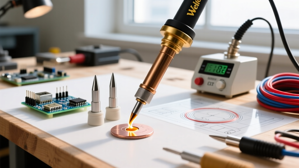
Premium stations, such as the Hakko FX-951 ($250) and the JBC CD-2BE ($350+), completely redesign how a soldering iron works by eliminating the physical gap between the heater, the sensor, and the tip.
Hakko's Composite Cartridge Design
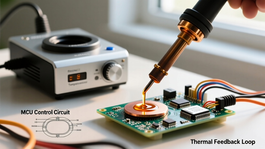
The Hakko FX-951 uses T18-style composite tips where the heating element, the ceramic thermocouple, and the copper core are integrated into a single cartridge. The sensor sits mere millimeters from the tip's apex. This reduces thermal latency from seconds down to milliseconds, allowing the station's PID controller to inject power exactly when the tip touches a thermal sink.
JBC's Exclusive Heating System
JBC takes this a step further with their C245 cartridges. The thermocouple is embedded directly inside the very tip of the copper core. Furthermore, JBC stations use a proprietary AC current-sensing mechanism that detects the exact moment the tip touches the PCB, delivering maximum wattage (up to 130W on the CD-2BE) instantaneously. This results in a thermal recovery time of under 2 seconds, even on heavy 10-layer motherboards.
Comparison Matrix: Thermal Recovery & Sensor Latency
The following table illustrates how different engineering approaches impact real-world performance metrics across the 2026 market landscape.
| Feature | Generic 60W ($15) | Pine64 Pinecil V2 ($26) | Hakko FX-951 ($250) | JBC CD-2BE ($350) |
|---|---|---|---|---|
| Sensor Type | NTC Thermistor | Fast-response Thermocouple | Composite Thermocouple | Embedded Thermocouple |
| Sensor Location | Heater Base (Remote) | Tip Base (Semi-Integrated) | Tip Shank (Integrated) | Tip Apex (Fully Integrated) |
| Control Algorithm | Simple Hysteresis | High-Frequency PID | Analog/Digital PID | Proprietary AC Triac Control |
| Thermal Recovery | 15 - 30 seconds | 4 - 6 seconds | 6 - 8 seconds | < 2 seconds |
| Heavy Ground Plane Handling | Fails (Cold Joints) | Moderate | Excellent | Flawless |
Tip Metallurgy: Why Cheap Tips Pit and Premium Tips Last
Understanding how a soldering iron works also requires a deep dive into tip metallurgy. A soldering tip cannot be made of pure solder, nor can it be made of bare copper, as molten solder will rapidly dissolve copper (a process known as leaching). Instead, tips rely on a complex layered structure:
- Copper Core: Provides rapid thermal conductivity.
- Iron Plating: Protects the copper from leaching. Thickness dictates lifespan.
- Chromium/Nickel Underlayer: Prevents molten solder from wicking up the shank of the tip.
The Budget Failure Mode: Iron Plating Erosion
Budget tips often feature a thin iron plating layer (10 to 25 microns). When exposed to modern, highly active lead-free fluxes and the high temperatures (350°C+) required for SAC305 solder, this thin layer rapidly oxidizes and pits. Once the flux breaches the iron and reaches the copper core, the tip develops deep craters and becomes unusable within weeks. For a comprehensive look on maintaining these layers, refer to the Hakko USA Soldering Tip Guide.
The Premium Advantage: Optimized Alloys
Premium manufacturers like JBC and Hakko utilize advanced metallurgical processes. Their tips feature thicker, denser iron plating (often exceeding 100 microns in high-wear areas) and proprietary copper alloys that resist thermal fatigue. While a generic tip might last for 50 hours of active soldering, a genuine JBC C245 cartridge can easily exceed 500 hours of heavy use, making the high upfront cost ($45+ per tip) highly cost-effective for production environments.
Real-World Failure Modes: Edge Cases to Watch
Even the best-engineered systems have failure modes. Here is what to watch for based on your chosen tier:
- Budget Iron Thermal Runaway: In cheap irons using basic triac dimmers, if the remote thermistor wire snaps or loses contact, the controller assumes the tip is cold and applies 100% power continuously. The tip will glow red hot, destroying the PCB and presenting a severe fire hazard.
- Pinecil V2 Tip Wobble: Because the Pinecil uses a friction-fit sleeve for its TS100-compatible tips, aggressive scrubbing during desoldering can cause the tip to seat improperly, introducing an air gap that ruins thermal transfer.
- Hakko T18 Shank Oxidation: If the chromium layer on the shank of a Hakko T18 tip is scratched during cleaning, solder will wick up the side of the tip, creating a messy bridge that is difficult to clean without damaging the composite sensor.
- JBC Handle Cord Fatigue: The ultra-flexible silicone cord on JBC handles is designed for extreme maneuverability, but in high-volume production environments where the cord is constantly dragged across sharp metal chassis edges, the internal wiring can fatigue and break near the strain relief.
Expert Verdict: When to Upgrade Your Station
So, how does a soldering iron work in the context of your specific needs? If you are primarily soldering simple through-hole components, repairing basic 2-layer hobby PCBs, or tinning wires, a smart budget iron like the Pinecil V2 provides 90% of the performance of a premium station at a fraction of the cost. Its fast PID loop easily overcomes the limitations of older budget designs.
However, if your work involves surface-mount device (SMD) rework, 0402 or 0201 components, heavy multilayer motherboards, or strict adherence to IPC Class 3 reliability standards, the thermal latency of budget irons will actively sabotage your yield. In these scenarios, the integrated cartridge architecture and instant thermal recovery of a JBC CD-2BE or Hakko FX-951 are not just luxuries—they are mandatory tools for professional reliability.