
The Thermodynamics of Soldering Iron Tips Types
Most electronics technicians treat soldering stations as simple temperature dials, assuming the digital readout perfectly reflects the working face of the tool. In reality, modern closed-loop PID controllers—like those found in the JBC CD-2BQE or Weller WE1010NA—measure the temperature of the internal heater core or a sensor embedded near the base of the cartridge. Because different soldering iron tips types possess vastly different thermal masses, surface areas, and distances from the sensor to the working face, a station calibrated for a heavy chisel tip will severely underperform or overshoot when swapped to a micro-conical tip without proper setup and recalibration.
According to the IPC J-STD-001 standard for soldered electrical assemblies, maintaining precise thermal profiles is critical to prevent intermetallic compound (IMC) overgrowth, pad delamination, or cold solder joints. This tutorial provides a deep-dive framework for selecting, setting up, and calibrating the four primary tip geometries used in modern electronics manufacturing and advanced DIY repair.
Core Soldering Iron Tips Types and Thermal Profiles
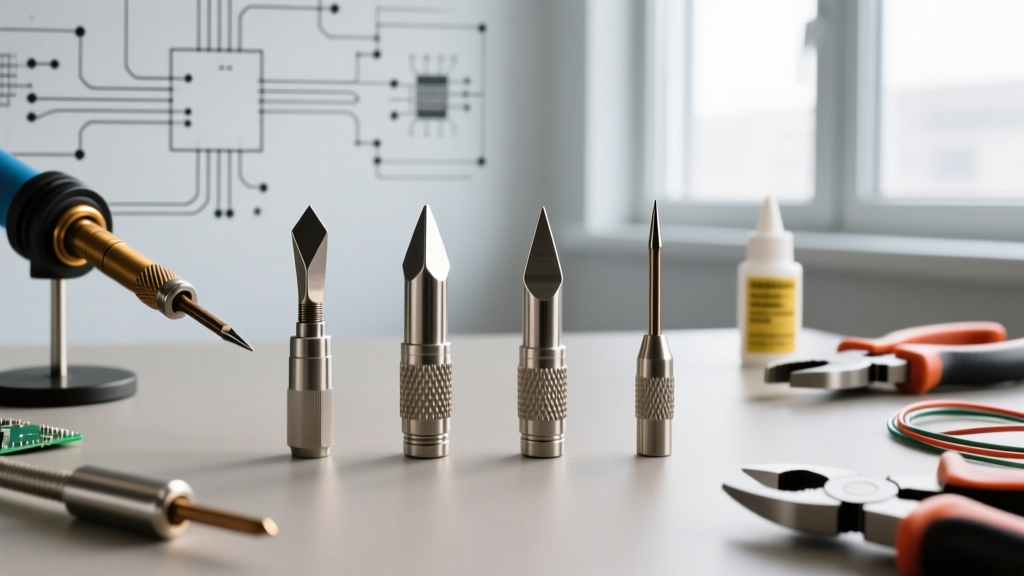
Before initiating any calibration sequence, you must understand the thermal bottleneck inherent in each geometry. The table below maps the primary tip types to their ideal applications, thermal characteristics, and baseline temperature offsets for SAC305 (lead-free) solder.
| Tip Geometry | Example Model | Thermal Mass | Sensor-to-Face Distance | Base Temp Offset (SAC305) | Primary Failure Mode |
|---|---|---|---|---|---|
| Chisel / Screwdriver | Hakko T18-D24 | High | Medium | 0°C to +5°C | Flux carbonization on flat face |
| Conical / Micro | Pace 1130-0008 | Very Low | Long (Bottleneck) | +15°C to +20°C | Thermal stall on ground planes |
| Bevel / Hoof | Weller RTW2 | High | Short | -5°C to 0°C | Solder bridging / uneven wear |
| Knife / Blade | JBC C210-115 | Medium | Very Short | 0°C | Edge pitting from abrasive cleaning |
1. Chisel and Screwdriver Tips
Chisel tips offer the highest surface area contact, making them the undisputed champions for 0805/0603 SMD components and standard through-hole leads. Because the thermal transfer is highly efficient, stations often require little to no positive offset. However, the flat face is prone to flux carbonization. If you are setting up a Hakko FX-951 with a T18-D24, maintain the station at 360°C for SAC305 and use brass wool rather than a wet sponge to prevent thermal shock micro-fractures in the iron plating.
2. Conical and Micro-Point Tips
Often mistakenly purchased by beginners for 'precision' work, conical tips actually suffer from a severe thermal bottleneck. The narrow shaft restricts heat flow from the heater core to the apex. When touching a high-thermal-mass pad, the apex temperature plummets, and the PID controller aggressively overshoots the core temperature to compensate, leading to rapid oxidation. Setup Rule: Only use conical tips for low-mass, fine-pitch components (like 0.4mm QFPs) and always apply a positive calibration offset of +15°C to ensure the apex reaches the solder's liquidus phase.
3. Bevel and Hoof Tips
Featuring a concave, scoop-like face, hoof tips are engineered for drag soldering SOIC and QFP chips. The concavity holds a reservoir of molten solder, leveraging fluid dynamics to pull excess solder away from IC pins via surface tension. Due to their high thermal mass and proximity to the sensor, they require slightly lower baseline settings to prevent scorching FR4 fiberglass substrates.
4. Knife and Blade Tips
The knife tip (such as the JBC C210-115) is a hybrid geometry. By using the flat side for broad heating and the sharp point for micro-soldering, it eliminates the need to swap tips mid-repair. Cartridge-style systems like JBC integrate the heater and sensor directly into the tip's shaft, meaning the knife profile responds to thermal drops in under 40 milliseconds, virtually eliminating the need for manual PID offset calibration.
Step-by-Step Calibration Tutorial for Mixed-Tip Setups
When operating a lab with multiple tip types, a one-size-fits-all temperature setting is a recipe for defective joints. Follow this calibration protocol using a dedicated tip thermometer (e.g., Hakko FG-100B, approx. $135) equipped with a K-type thermocouple.
- Preparation and Tinning: Power on the station and set it to the target alloy's liquidus temperature + 40°C (e.g., 380°C for SAC305, which melts at ~217°C). Apply a generous amount of high-flux, rosin-based solder (Sn63/Pb37 is preferred for calibration due to its sharp eutectic phase change) to coat the working face entirely.
- Thermal Paste Application: Apply a microscopic dot of thermally conductive paste (like Wakefield-Vette 120-2) to the center of the tip's working face. This eliminates the air gap between the tip and the thermocouple bead, which can otherwise skew readings by up to 25°C.
- Thermocouple Placement: Press the K-type sensor bead firmly into the thermal paste on the exact contact point of the tip. Hold for 15 seconds until the reading on the FG-100B stabilizes.
- Calculate and Apply Offset: If the station reads 380°C but the thermocouple reads 365°C (common with long conical tips), you have a -15°C delta. Access your station's hidden calibration menu (often accessed by holding a specific button sequence or using a proprietary calibration dongle) and input the +15°C offset.
- Thermal Recovery Verification: Wipe the tip on brass wool. The temperature should drop momentarily and recover to within 5°C of the setpoint within 3 to 5 seconds on modern cartridge stations, or 8 to 12 seconds on traditional ceramic heater stations.
Expert Insight: Never calibrate a station using a dry, oxidized tip. Iron oxide acts as a thermal insulator. If your tip exhibits 'black tip syndrome' (a dark, non-wetting crust), you must chemically reduce it using a tip tinner/cleaner (such as Edsyn TC1) containing mild abrasives and reducing agents before attempting any thermocouple measurements.
Preventing Premature Tip Degradation Across Geometries
Different soldering iron tips types fail in unique ways based on their geometry and the thermal stress placed upon them. Understanding these failure modes is critical for long-term lab setup and maintenance.
Iron Plating Erosion (The SAC305 Effect)
Modern lead-free solders, particularly those with high silver content (SAC305 or SAC405), are highly aggressive to the iron plating that protects the copper core of the tip. Chisel and bevel tips, which are often held against pads for longer durations to transfer bulk heat, suffer from 'coring'—where the solder literally dissolves the iron plating, exposing the soft copper underneath. Once the copper is exposed, the tip will pit and degrade within hours. Prevention: Never exceed 380°C for SAC alloys, and always leave a thick layer of sacrificial solder on the tip before powering down the station.
Thermal Shock Cracking in Micro Tips
Conical and micro-point tips have minimal thermal mass. When a technician uses a wet cellulose sponge to clean a 400°C micro tip, the rapid localized cooling causes the iron plating to contract faster than the copper core, resulting in microscopic circumferential cracks. These cracks allow flux to penetrate and corrode the internal copper heater sleeve. Prevention: Transition entirely to dry brass wool (copper or brass shavings) for all tip geometries, as recommended by the NASA-STD-8739.3 workmanship requirements for soldering stations.
Advanced Setup: Matching Tip to Pad Thermal Demand
The ultimate test of your setup and calibration is matching the tip's thermal delivery to the PCB's thermal demand. A common edge case in 2026 electronics repair involves multilayer boards with heavy internal copper pours (ground planes). If you attempt to solder a through-hole connector pin connected to an 8-layer ground plane using a standard 1.6mm conical tip, the PCB will act as an infinite heat sink. The tip's apex will drop below the solder's liquidus point, resulting in a dull, grainy 'cold' joint, even if the station's digital display claims 400°C.
The Solution: Switch to a high-mass bevel or a wide chisel tip (e.g., 3.2mm or 4.8mm). The increased cross-sectional area of the copper core inside the tip provides a larger thermal reservoir, allowing the PID controller to pump continuous wattage into the joint without the tip face stalling. For extreme cases, pre-heating the PCB from the bottom to 120°C using an infrared preheater (like the Quick 853A) reduces the thermal delta the iron must overcome, preserving both your tip plating and the PCB's vias.
Summary Checklist for Lab Managers and Technicians
- Audit your inventory: Discard any conical tips used for heavy through-hole work; replace with chisel profiles.
- Calibrate per geometry: Document the specific PID offset required for every tip model in your lab's setup log.
- Standardize cleaning: Remove all wet sponges from soldering stations to prevent thermal shock cracking.
- Monitor alloy temps: Strictly enforce a 360°C maximum for Sn63/Pb37 and a 380°C maximum for SAC305 to prevent iron dissolution.
By treating soldering iron tips types not as interchangeable accessories, but as distinct thermal transfer devices requiring specific calibration and setup protocols, you will drastically reduce joint defects, extend tip lifespan, and achieve consistent, IPC-compliant soldering results.