
The Architecture of Alientek Smart Irons
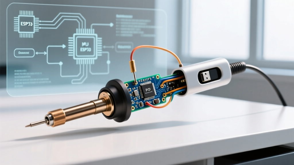
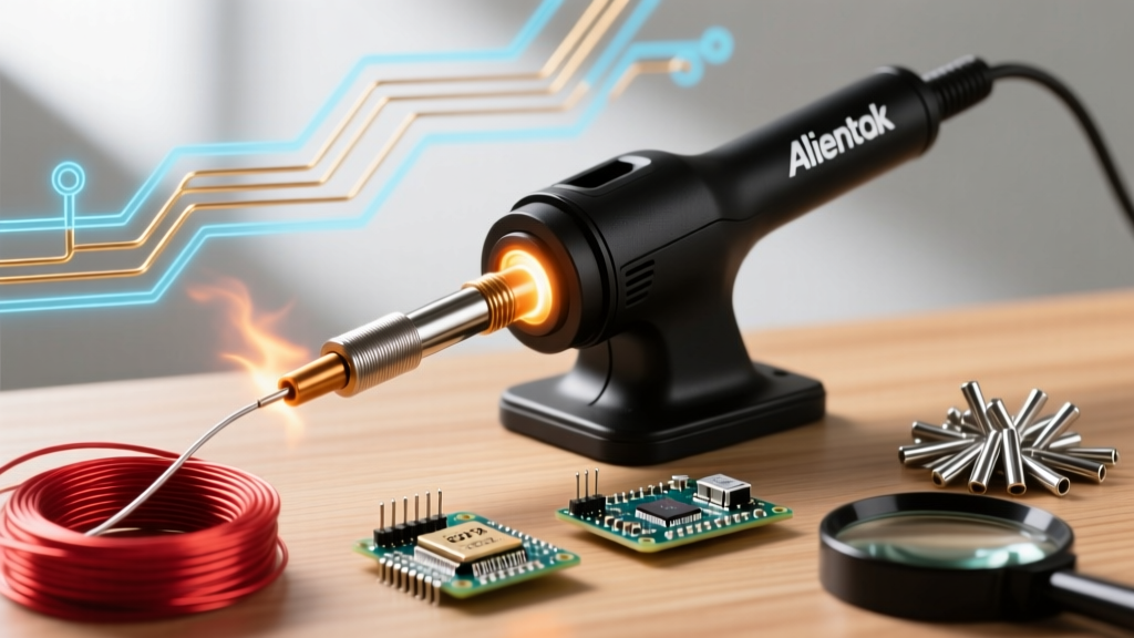
Alientek has carved a distinct niche in the portable electronics repair market by engineering smart soldering irons that rival established brands like Pine64 and Miniware. Unlike traditional transformer-based stations, Alientek irons rely on high-frequency Pulse Width Modulation (PWM) driven by an internal STM32 ARM Cortex microcontroller. This architecture allows for rapid thermal recovery and precise temperature profiling, but it also introduces complex failure modes related to USB-C Power Delivery (PD) negotiation, thermocouple drift, and firmware corruption.
As of 2026, the proliferation of 140W GaN chargers and USB PD 3.1 standards has shifted the diagnostic landscape. Troubleshooting an Alientek soldering iron requires moving beyond basic visual inspections and utilizing multimeters, USB PD analyzers, and DFU (Device Firmware Upgrade) protocols. This guide provides a deep-dive diagnostic framework for resolving the most critical hardware and software faults in the Alientek ecosystem.
Diagnostic Matrix: Symptoms and Multimeter Readings
Before disassembling the handle or flashing new firmware, map your specific symptom to the diagnostic matrix below. This will save time and prevent unnecessary hardware replacements.
| Symptom | Root Cause | Diagnostic Action & Expected Reading |
|---|---|---|
| Screen shows 'DC' or low-wattage warning | USB-C PD negotiation failed; fallback to 12V/24V DC mode | Use USB-C tester to verify charger broadcasts 20V/3A or 20V/5A PDO |
| Tip heats unevenly or overshoots target temp | K-type thermocouple degradation or ADC calibration drift | Measure thermocouple pins; expect ~0.5Ω to 2.0Ω resistance |
| Iron powers on but tip remains completely cold | Heater cartridge burnout or internal MOSFET failure | Measure heater pins; expect 6.5Ω to 8.0Ω. 'OL' indicates dead cartridge |
| Screen frozen on boot logo or completely black | Corrupted firmware or STM32 bootloader crash | Connect to PC; check Device Manager for 'STM32 BOOTLOADER' or DFU device |
| OLED screen exhibits ghosting or burn-in | Static UI elements left on display during extended idle periods | Visual inspection; enable auto-dim/sleep features in settings menu |
Resolving USB-C Power Delivery (PD) Negotiation Failures
The most common issue reported with Alientek smart irons is the failure to negotiate the correct power profile. These irons require a 20V Power Data Object (PDO) to achieve their rated 65W or 100W output. If the iron defaults to a lower voltage (like 5V or 12V), the PWM duty cycle maxes out immediately, resulting in sluggish thermal recovery and an on-screen warning.
Testing the Cable and Power Brick
Do not assume a USB-C cable is capable of 100W delivery simply because the connector fits. According to the USB Implementers Forum (USB-IF) specifications, any cable rated for currents above 3A must contain an embedded E-marker chip. If your Alientek iron requests 20V/5A (100W) and the cable lacks a valid E-marker, the PD sink controller inside the iron will reject the connection to prevent the cable from melting, defaulting to a safe 60W (20V/3A) or lower profile.
- Verify the Charger: Connect a USB-C multimeter tester (such as the FNIRSI FNB58 or MakerHawk) between the GaN charger and the iron. Read the advertised PDOs. You must see a 20V profile listed.
- Check the E-Marker: Use the tester's cable read function. If the cable reads 'No E-Marker' or '3A Max', replace it with a certified 5A/100W USB-C to USB-C cable.
- Inspect the Iron's USB-C Port: Use a wooden toothpick to clear out pocket lint or flux residue from the iron's receptacle. Compacted debris can short the CC1/CC2 configuration pins, preventing the PD handshake entirely.
Heater Cartridge and Thermocouple Diagnostics
Alientek irons utilize a split-pin architecture at the tip receptacle. The outer sleeve acts as the ground shield, while the inner pins carry the high-current PWM signal for the heater and the microvolt-level analog signal from the K-type thermocouple. Because the thermocouple relies on the Seebeck effect to generate voltage based on temperature differentials, any increase in circuit resistance will cause the STM32's Analog-to-Digital Converter (ADC) to misread the temperature.
When to Replace the Tip Assembly
If your iron exhibits thermal runaway (heating past the set point) or refuses to heat while displaying a 'Sensor Error', perform a cold resistance test:
- Heater Resistance: Set your multimeter to Ohms (Ω). Place probes on the two dedicated heater pins. A healthy Alientek cartridge should read between 6.5Ω and 8.0Ω. A reading of 'OL' (Open Loop) means the internal nichrome wire has snapped, requiring a full tip replacement.
- Thermocouple Resistance: Place probes on the thermocouple pins. The reading should be very low, typically 0.5Ω to 2.0Ω. If you read high resistance or 'OL', the internal K-type wire has degraded or broken at the crimp joint.
- Ground Continuity: Check continuity between the outer metal sleeve of the tip and the ground pin on the USB-C/DC input. This ensures the hardware watchdog and ESD protection circuits remain intact.
Expert Warning: Never use a wire cutter or abrasive sandpaper to scrape oxidation off an Alientek smart tip. This destroys the protective iron plating over the copper core. Once the copper is exposed to molten solder, it will dissolve rapidly (leaching), permanently ruining the tip's thermal transfer properties. Always use damp cellulose sponges or brass wire wool.
Firmware Recovery via STM32 DFU Mode
Because Alientek irons are essentially embedded systems, a failed over-the-air update, a sudden power loss during a flash, or a corrupted configuration file can 'brick' the device. Fortunately, the underlying STM32F103 microcontroller features a hardware-level ROM bootloader that cannot be overwritten.
Step-by-Step Unbricking Procedure
To recover a dead Alientek iron, you must force it into Device Firmware Upgrade (DFU) mode and flash a clean factory binary.
- Enter DFU Mode: Unplug the iron. Press and hold the 'A' (front/primary) button. While holding the button, connect the iron to a PC via a data-capable USB-C cable. Keep holding the button for 3 seconds after plugging it in, then release.
- Verify PC Recognition: Open your operating system's Device Manager (Windows) or run
lsusb(Linux/macOS). You should see a device listed as 'STM32 BOOTLOADER' or 'DFU in FS Mode'. - Flash the Firmware: Download the latest official Alientek firmware binary (
.bin) from the manufacturer's repository. Use the open-sourcedfu-utilcommand-line tool to push the firmware to the MCU's flash memory at the correct hex address.
The standard command line syntax for STM32 DFU flashing is:
dfu-util -a 0 -s 0x08000000:leave -D alientek_firmware_v2.x.bin
For a comprehensive breakdown of the USB DFU protocol and memory addressing for STM32 chips, refer to the STMicroelectronics AN3156 Application Note. The :leave parameter is critical, as it instructs the microcontroller to jump to the newly flashed application code immediately after the transfer completes, rather than waiting for a manual reset.
Preventative Maintenance per IPC Standards
To maximize the lifespan of your Alientek soldering iron and its interchangeable tips, align your maintenance routine with the IPC J-STD-001 guidelines for soldered electrical assemblies. Proper thermal management and chemical handling are paramount.
The 5-Minute Post-Soldering Routine
- Heavy Tinning Before Shutdown: Before turning off the iron, apply a generous amount of 63/37 (Sn/Pb) or SAC305 (lead-free) flux-core solder to the entire working surface of the tip. This creates a sacrificial oxidation barrier that protects the iron plating while the tip cools down to room temperature.
- Flux Residue Removal: If you use aggressive no-clean or water-soluble fluxes, wipe the handle and the tip receptacle with 99% isopropyl alcohol (IPA). Flux vapors can condense inside the USB-C port or on the OLED screen, leading to corrosion and capacitive touch failures over time.
- Strain Relief Inspection: Alientek irons are often used with stiff silicone cables. Routinely inspect the cable strain relief boot at the base of the handle. If you notice micro-tears in the silicone, wrap it with self-fusing silicone tape to prevent internal wire fatigue and eventual short circuits.
Managing OLED Screen Burn-In
The high-contrast OLED displays on Alientek irons are susceptible to phosphor burn-in if left on a static menu screen for hours. Always configure the 'Auto-Sleep' timer to 2 minutes and the 'Shutdown' timer to 10 minutes. If your model supports custom UI themes, rotate the placement of the temperature readouts or enable a pixel-shift screensaver to distribute the wear evenly across the display matrix.
By understanding the interplay between USB-C PD protocols, K-type thermocouple physics, and STM32 firmware architecture, you can transform a seemingly dead Alientek soldering iron back into a precision repair tool. Keep a digital multimeter, a USB PD tester, and a spool of SAC305 solder on your bench, and you will be equipped to handle any fault the device throws your way.