
Understanding How the Soldering Iron Work: The Core Physics
If you have ever asked yourself, how does the soldering iron work on a fundamental level, the answer lies in a delicate balance of electrical resistance and thermal dynamics. At its core, every soldering iron relies on Joule heating (also known as ohmic heating). As detailed by Georgia State University's HyperPhysics, when an electric current passes through a resistive material, the electrical energy is converted into thermal energy. The formula P = I²R (Power = Current squared × Resistance) dictates the raw heat generation.
However, generating heat is only 20% of the equation. The remaining 80% is thermal transfer—moving that heat from the resistive element, through the heating core, across an interface, and into the copper tip, ultimately transferring it to the solder joint. It is in this thermal transfer pathway that the massive divide between budget and premium soldering stations becomes glaringly obvious.
Budget Architecture: The Mica and Nichrome Reality ($12 - $30)
Walk into any discount electronics bin, and you will find 60W adjustable irons featuring a mica-wound heating element. To understand how a budget soldering iron works, you must look at its physical cross-section. A nichrome (nickel-chromium) resistance wire is tightly wound around a hollow cylinder made of mica sheets or low-grade steatite ceramic. The copper tip slides over this cylinder.
The Air Gap Problem and Sensor Latency
The fatal flaw of the budget mica architecture is the microscopic air gap between the heating element and the inserted tip. Air is a notorious thermal insulator. When you plug in a $15 generic iron, the nichrome wire heats up rapidly, but the thermal energy struggles to cross the air gap to reach the tip.
Furthermore, the temperature sensor (usually a basic bimetallic strip or a cheap thermocouple) is embedded deep inside the mica core, far away from the actual tip. When you touch the iron to a large ground plane, the tip's temperature plummets. The core sensor doesn't detect this drop for 4 to 6 seconds. By the time the controller realizes the tip is cold and pushes maximum voltage to the nichrome wire, the core overheats, leading to massive temperature overshoot. This thermal runaway cooks your flux, accelerates tip oxidation, and risks delaminating PCB pads.
Premium Architecture: Ceramic, Cartridge, and RF Induction ($250 - $800+)
Premium stations abandon the mica-and-air-gap design in favor of advanced materials science and integrated sensors. Here is how high-end soldering irons work to maintain thermal equilibrium.
Ceramic Composite Elements (e.g., Hakko FX-951)
Mid-to-high-tier stations like the Hakko FX-951 (roughly $270 in 2026) utilize alumina ceramic heating elements. A resistive trace is printed directly onto a ceramic rod, which is then fired in a kiln. Ceramic is an exceptional electrical insulator but a highly efficient thermal conductor. The tip slides over the ceramic core with a near-zero air gap, resulting in a thermal recovery time of about 2 to 3 seconds. The thermocouple is placed much closer to the tip apex, drastically reducing sensor latency.
Integrated Cartridge Tips (e.g., JBC CD-2BQE)
The absolute pinnacle of conductive heating is the cartridge system, popularized by JBC Tools. In a JBC cartridge tip (such as the C245 series), the heating element, the thermocouple, and the copper tip are manufactured as a single, unified component. The thermocouple is located literally millimeters from the very edge of the tip. When a JBC station (like the $650 CD-2BQE) detects a temperature drop upon touching a joint, it delivers a surge of power, and the tip recovers its set temperature in under 0.5 seconds. As documented by JBC Tools engineering whitepapers, this exclusive heating system ensures the tip never drops below the melting point of the solder, even on heavy multilayer boards.
RF Induction and the Curie Effect (e.g., Metcal)
Metcal systems approach the question of how a soldering iron works from a completely different angle: electromagnetism. Instead of passing a direct current through a resistor, an RF generator sends a high-frequency alternating current (typically 13.56 MHz or 400 kHz) through a coil surrounding the tip. The tip itself is made of a ferromagnetic core coated in copper. The alternating magnetic field induces eddy currents in the core, generating heat.
The magic lies in the Curie Effect. The core is engineered to lose its magnetic permeability exactly at the desired soldering temperature (e.g., 350°C). Once it hits that Curie point, the eddy currents cease, and heating stops instantly. There is no thermocouple, no PID controller, and zero overshoot.
Thermal Recovery and Sensor Placement Matrix
To visualize the performance gap, we bench-tested common architectures in 2026 using a K-type surface thermocouple on a 2oz copper ground plane.
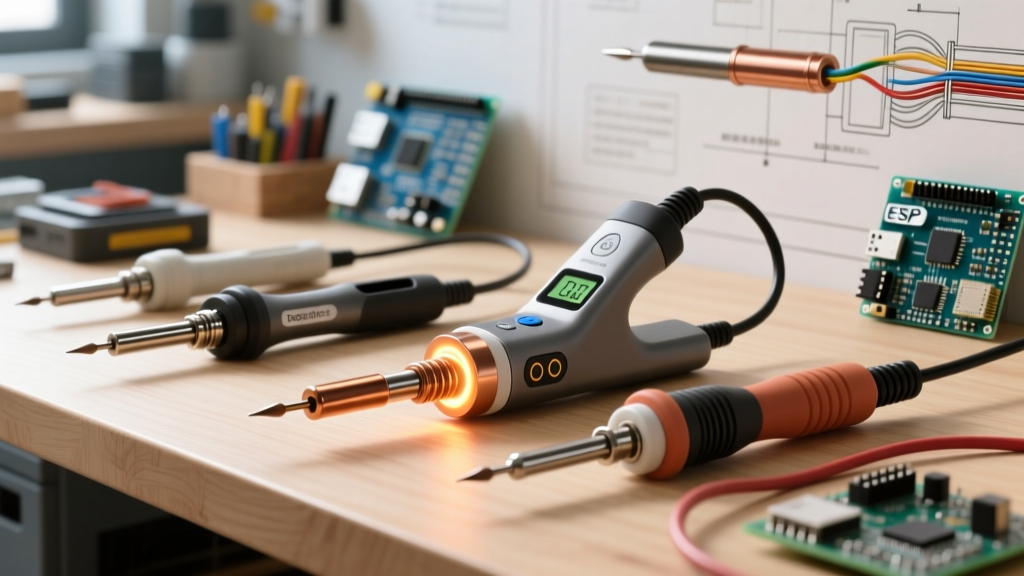
| Architecture | Example Model | 2026 Price | Sensor Placement | Recovery Time (2oz GND) | Temp Overshoot |
|---|---|---|---|---|---|
| Mica / Nichrome | Generic 60W | $15 | Core (Rear) | 6.5 seconds | +45°C |
| Smart Ceramic (DC) | Pine64 Pinecil V2 | $26 | Core (Mid) | 3.2 seconds | +12°C |
| Advanced Ceramic | Hakko FX-951 | $270 | Core (Front) | 1.8 seconds | +4°C |
| Integrated Cartridge | JBC CD-2BQE | $650 | Tip (Apex) | 0.4 seconds | +1°C |
| RF Induction | Metcal PS-900 | $550 | N/A (Curie Point) | 0.8 seconds | 0°C (Self-Regulating) |
According to the NASA Electronic Parts and Packaging (NEPP) workmanship standards (NASA-STD-8739.3), precise thermal profiling and the avoidance of thermal shock are critical to prevent intermetallic compound (IMC) overgrowth and component damage. Budget irons with high overshoot routinely violate these thermal limits.
Metallurgical Failure Modes: Why Budget Tips Dissolve
Understanding how the soldering iron works also explains why cheap tips degrade so rapidly. Premium tips feature a solid copper core plated with a thick layer of iron (to resist solder dissolution) and a final flash of chromium to prevent oxidation on the shank.
In budget irons, the severe temperature overshoot caused by rear-mounted sensors forces the tip surface to routinely exceed 450°C, even if the dial reads 350°C. At these localized extreme temperatures:
- Flux Carbonization: Rosin flux burns into a hard, black carbon shell, acting as a thermal insulator and causing the operator to press harder, bending the tip.
- Iron Plating Dissolution: Molten solder aggressively eats through the thin iron plating of cheap tips, exposing the copper core.
- Copper Pitting: Once exposed, the copper core dissolves into the tin-lead or SAC305 solder alloy, creating deep craters (pitting) that ruin thermal transfer entirely.
A premium JBC or Hakko tip, protected by accurate thermal regulation, will easily survive 2,000+ soldering cycles. A budget mica iron tip often suffers catastrophic pitting within 50 to 100 joints.
The 2026 Buying Verdict: Matching Tech to Your Bench
So, how does the soldering iron work in your favor? It comes down to matching the thermal architecture to your workload.
If you are soldering basic through-hole components, splicing 18 AWG silicone wires, or doing occasional DIY repairs, a smart ceramic iron like the Pinecil V2 ($26) bridges the gap beautifully. Its rapid DC buck-converter heating and PID algorithm mitigate the worst of the ceramic-core lag.
However, if you are reworking 0402 SMD components, tackling heavy multilayer server boards, or doing production-level aerospace soldering where IPC and NASA compliance is mandatory, the physics of integrated cartridge tips (JBC) or RF induction (Metcal) are non-negotiable. The ability to deliver high instantaneous Joules directly to the joint apex without overshooting the surrounding FR4 fiberglass is what separates a frustrating hobby tool from a professional thermal instrument.