
The Reality of the JBC T245: Handle vs. Station
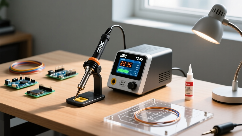
Before diving into the setup and calibration tutorial, we must address a common industry misnomer. When professionals refer to the JBC T245 soldering station, they are technically conflating the handle with the base unit. The T245 (specifically the T245-A) is the precision soldering handle designed to accept JBC's proprietary C245 cartridge tips. To function, this handle must be paired with a compatible JBC base station, most commonly the JTSE-2B, JBCD-2B, or the advanced JNA-2 series.
As of 2026, a genuine JBC T245-A handle retails for approximately $105 to $115, while a flagship JTSE-2B station costs between $550 and $650. This modular ecosystem is what gives JBC its legendary 2-second thermal recovery time. However, out-of-the-box performance is only as good as your initial setup, cartridge selection, and digital offset calibration. This guide provides a lab-grade procedure for configuring your T245 ecosystem to meet stringent IPC J-STD-001 workmanship requirements.
Phase 1: Hardware Setup and Ergonomic Configuration
Proper hardware integration prevents premature heater degradation and ensures the auto-sleep features function correctly.
- Handle Connection: Align the 5-pin DIN connector on the T245 cable with the station's front receptacle. Push firmly until the collar clicks. Never twist the DIN connector, as bending the internal sensing pins will result in persistent 'H1' (Cartridge Not Detected) errors.
- Stand Integration: The T245 handle is designed to work with Hall-effect auto-sleep stands like the JBC PHSE. Ensure the magnetic ring on the silicone grip of the T245 aligns with the sensor in the stand cradle. If the station does not drop to standby temperature when the iron is holstered, rotate the handle 180 degrees in the cradle to align the internal magnet with the stand's sensor.
- Cable Management: The T245 features a low-friction, burn-proof silicone cable. Route the cable through the station's rear cable guide to prevent the cord from dragging across hot components or knocking over flux dispensers on your workbench.
Phase 2: C245 Cartridge Selection Matrix
Calibration is useless if you are using the wrong thermal mass for your PCB. JBC's C245 cartridges house the heating element directly inside the tip, eliminating the thermal lag found in traditional ceramic-core irons. Below is a decision matrix for selecting the correct C245 cartridge based on common 2026 electronics repair scenarios.
| Cartridge Model | Tip Geometry & Size | Primary Application | Thermal Mass Rating |
|---|---|---|---|
| C245-900 | Micro-Blade (2.5mm) | 0402/0603 SMD passives, fine-pitch IC pins | Low (Fast ramp-up, low heat capacity) |
| C245-114 | K-Blade / Knife (3.0mm) | Drag soldering QFPs, cleaning edge connectors | Medium (Balanced lateral heat distribution) |
| C245-05 | Micro-Chisel (0.5mm) | 0201 components, micro-BGA rework, jumper wires | Very Low (Precision pinpoint heating) |
| C245-754 | Heavy Conical (4.0mm base) | Through-hole with moderate ground planes | High (Sustained heat delivery) |
| C245-875 | Heavy Chisel (5.0mm) | Multi-layer PCB ground planes, thick wire tinning | Maximum (Requires full 75W station output) |
Phase 3: The Digital Offset Calibration Procedure
Unlike legacy analog stations that require you to open the chassis and turn a physical potentiometer with a ceramic screwdriver, JBC stations utilize a digital offset calibration system. While JBC factories calibrate these units to within ±2°C, environmental factors, specific tip geometries, and thermocouple variances necessitate field verification.
Tools Required for Calibration
- A calibrated K-Type thermocouple tip thermometer (e.g., Hakko 191 or Weller WSD-1).
- Thermal conductive paste or high-temperature aluminum tape (to eliminate air gaps between the tip and thermocouple).
- SAC305 (Lead-Free) or Sn63/Pb37 (Leaded) test solder.
Step-by-Step Calibration Workflow
Step 1: Thermal Equilibrium Setup
Insert a brand-new, medium-mass cartridge (like the C245-114) into the T245 handle. Set the station to 350°C, the standard operating temperature for SAC305 lead-free solder as recommended by modern NASA and IPC soldering workmanship standards. Allow the iron to idle at this temperature for exactly 60 seconds to ensure the internal heater and outer copper shell reach full thermal equilibrium.
Step 2: Thermocouple Coupling
Apply a minuscule dab of thermal paste to the K-type thermocouple bead. Press the bead firmly against the working surface of the C245 tip and hold it perfectly still. Expert Tip: Do not rely on ambient air readings or simply resting the thermocouple on the tip; the air gap will yield false readings up to 15°C lower than the actual tip temperature.
Step 3: Accessing the Offset Menu
On the JTSE or JBCD station, press and hold the main rotary encoder knob for 5 seconds until the display flashes. Navigate to the 'CAL' or 'Offset' submenu. The screen will display the current factory offset (usually 00 or a small integer).
Step 4: Applying the Offset
Compare the station's digital readout (350°C) with your thermocouple's physical reading. If your thermocouple reads 346°C, you have a -4°C variance. Use the rotary knob to dial in a +4°C offset on the station. The station will now drive the heater to 354°C internally to deliver a true 350°C at the tip surface.
Lab Manager Note: Under IPC J-STD-001 guidelines, soldering equipment must be verified at least every 6 months or whenever the tip style is changed to a drastically different thermal mass. Always lock your station's calibration menu with a 4-digit PIN to prevent unauthorized technicians from altering the offset.
Phase 4: Advanced Station Parameter Tuning
To maximize the lifespan of your $45 C245 cartridges and the $110 T245 handle, you must configure the station's power management parameters. Oxidation is the primary killer of JBC cartridges, and oxidation rates double for every 50°C increase in idle temperature.
- Sleep Temperature (SLP): Set to 180°C. This is hot enough to prevent thermal shock when you pick up the iron, but cool enough to virtually halt flux carbonization and tip oxidation.
- Standby Timer (STB): Set to 9 minutes. If the Hall-effect stand does not detect the handle for 9 minutes, the station drops to 180°C.
- Auto-Off Timer (OFF): Set to 30 minutes. If the handle remains in the stand for 30 minutes, the station cuts power to the heater entirely, requiring a manual knob press to wake.
- Boost Mode (if supported by station): Configure the 'Boost' parameter to +20°C for 40 seconds. This allows you to temporarily push a C245-875 chisel tip to 380°C to sink heat into a heavy ground plane via a foot pedal or button press, without permanently subjecting the tip to high-temperature degradation.
Phase 5: Troubleshooting T245 Error Codes & Failure Modes
Even with perfect calibration, the T245 handle operates in harsh environments. Understanding JBC's proprietary error codes will save you from unnecessarily replacing expensive components.
Error Code: H1 (Cartridge Not Detected)
Cause: The station cannot read the EEPROM or thermal sensor inside the C245 cartridge.
Resolution: First, remove the cartridge and inspect the 4 internal contacts inside the T245 handle collet. Clean them with 99% isopropyl alcohol and a lint-free swab. If the contacts are clean and the error persists across multiple known-good cartridges, the internal wiring harness inside the T245 handle has fractured near the strain relief. The handle must be replaced.
Error Code: H2 (Heater Open Circuit / Over-Temperature)
Cause: The internal ceramic heater embedded within the C245 cartridge has physically cracked or burned out.
Resolution: This is a cartridge failure, not a station or handle failure. Discard the C245 tip. Warning: Do not attempt to run the station without a cartridge installed, as the open circuit will immediately trigger an H2 fault and lock the station until a valid load is detected.
Thermal Lag on Heavy Ground Planes
Cause: You are using a low-mass tip (e.g., C245-900) on a multi-layer PCB with high thermal conductivity.
Resolution: Do not compensate by raising the station temperature to 400°C+. This will instantly oxidize the tip plating. Instead, switch to a high-mass cartridge like the C245-875 or C245-05 (for localized thermal injection) and utilize pre-heating (a bottom-side PCB preheater set to 130°C) to reduce the delta-T required by the T245 iron.
Final Verification and Maintenance
Once your JBC T245 setup is calibrated and configured, perform a final practical test. Melt a small puddle of SAC305 solder on a scrap FR4 board. The solder should transition from solid to a shiny, mirror-like liquid state in under 1.5 seconds upon contact with the tip. If the solder turns dull or requires prolonged dwelling, re-verify your thermocouple offset and ensure your station's firmware is updated to the latest 2026 revision via the JBC USB service port.
For ongoing maintenance, always tin the C245 cartridge with a generous blob of leaded solder (Sn63/Pb37) before placing it into the auto-sleep stand. The leaded solder acts as a sacrificial oxidation barrier, ensuring your meticulously calibrated JBC T245 station delivers flawless, IPC-compliant joints every time you pick up the handle.
For further reading on advanced thermal profiles and equipment validation, refer to the official JBC Tools technical documentation and your organization's internal quality management system.