
The Real Answer: How Hot Does a Soldering Iron Get?
When hobbyists and professionals ask, "how hot does soldering iron get?", the literal answer is usually between 400°C and 480°C (752°F to 896°F) for maximum dial settings. However, treating maximum temperature as a primary performance metric is one of the most common misconceptions in electronics assembly. In 2026, with the widespread adoption of complex multilayer PCBs and demanding lead-free alloys, the true measure of a soldering station is not how hot it can get, but how fast it can recover its heat when applied to a massive thermal ground plane.
This guide breaks down the thermal dynamics of budget versus premium soldering stations, exploring why a $25 generic iron set to 450°C will destroy your PCB pads, while a $320 premium station set to 380°C will create a flawless, IPC-compliant joint in seconds.
The Baseline: Operating vs. Maximum Temperatures
To understand tool requirements, we must first look at the metallurgy of the solder itself. The iron's temperature must always exceed the solder's liquidus point (the temperature at which it fully melts) to allow for proper wetting and intermetallic compound (IMC) formation.
- Sn63/Pb37 (Eutectic Leaded): Melts at 183°C (361°F).
- SAC305 (Lead-Free Standard): Melts at 217°C (423°F).
- Sn96.5/Ag3.0/Cu0.5 (High-Reliability Lead-Free): Melts at 217°C - 220°C.
The industry-standard rule of thumb, supported by IPC J-STD-001 requirements, dictates that the soldering iron tip should be set approximately 100°C to 150°C above the solder alloy's liquidus point. For standard SAC305 lead-free solder, this means an optimal working temperature of roughly 350°C to 380°C. Cranking an iron to its absolute maximum of 480°C is rarely necessary and almost always detrimental.
Budget vs. Premium Thermal Matrix
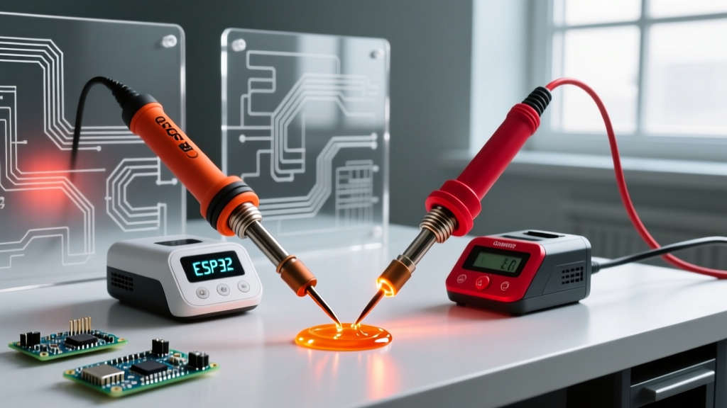
The difference between a budget iron and a premium station lies in thermal mass, sensor placement, and PID (Proportional-Integral-Derivative) controller logic. Below is a comparative analysis of three common tiers found on workbenches today.
| Station Tier | Model Example (2026 Market) | Avg. Price | Max Temp | Thermal Recovery (50°C Drop) | Sensor Location |
|---|---|---|---|---|---|
| Budget | Generic 60W Adjustable (Amazon Basics style) | $18 - $25 | 450°C | 45+ seconds | Ceramic heater shaft (Handle) |
| Mid-Tier | Hakko FX-888D | $110 - $130 | 480°C | 8 - 12 seconds | Tip base thermocouple |
| Premium | JBC CD-2BE (C245 Cartridge) | $310 - $350 | 450°C | < 2 seconds | Integrated inside tip cartridge |
The "Max Temp" Trap in Budget Irons
When you use a $20 budget soldering iron and turn the dial to 450°C to compensate for a slow thermal recovery on a large ground plane, you trigger a destructive cycle known as thermal overshoot.
Because the temperature sensor in a budget iron is located deep inside the ceramic heating element (near the handle), it cannot accurately read the temperature of the copper tip. When you touch the tip to a cold, multi-layer PCB, the tip temperature instantly plummets to 200°C. The handle sensor, insulated from this sudden drop, doesn't register the change immediately. The heater stays on full blast. By the time the sensor realizes the tip is cold and the iron recovers, the tip has overshot to well over 500°C, instantly charring your flux and oxidizing the iron plating.
Expert Insight: A budget iron's 450°C dial setting does not mean the tip maintains 450°C. It means the heating element is being driven to extreme limits to force a poorly conductive mechanical joint to transfer heat, resulting in wild temperature swings of over 100°C during a single soldering cycle.
Why Premium Cartridge Systems Dominate High-Heat Tasks
Premium stations like the JBC CD-2BE or Weller WX series solve the thermal lag problem through integrated cartridge technology. In these systems, the heating element, the thermocouple sensor, and the copper tip are manufactured as a single, unified component.
Because the sensor is located millimeters from the very point of contact, the station's microprocessor detects a temperature drop the exact millisecond the tip touches a copper pour. The system dumps high current into the heater, recovering a 50°C drop in under two seconds. This allows you to solder heavy 10-gauge wires or massive ground planes at a much lower, safer baseline temperature (e.g., 380°C) because the iron never loses its thermal momentum. You are relying on thermal recovery speed rather than brute-force maximum heat.
High-Temperature Failure Modes: What Happens at 450°C+?
Understanding how hot a soldering iron gets is critical because exceeding 400°C for prolonged periods accelerates three distinct failure modes in electronics assembly:
1. Flux Charring and Voiding
Modern rosin-based and water-soluble fluxes are chemically engineered to activate between 180°C and 250°C. If your iron tip is sitting at 450°C, the flux will instantly vaporize and carbonize before the solder alloy even reaches its liquidus point. This leaves a hard, black carbon residue that prevents wetting, leading to cold, brittle joints and excessive solder splatter.
2. Exponential Tip Oxidation (Pitting)
Soldering iron tips are not solid copper; they are copper cores plated with a thin layer of iron to prevent the solder from dissolving the copper. According to Hakko's official soldering tip care guidelines, the rate of tip oxidation doubles for every 50°C increase above 350°C. At 450°C, the molten SAC305 solder aggressively dissolves the iron plating, creating microscopic pits. Once the solder breaches the iron layer and reaches the copper core, the tip is destroyed and will no longer accept tinning.
3. PCB Delamination and Pad Lifting
Standard FR4 fiberglass PCB material has a Glass Transition Temperature (Tg) typically ranging from 130°C to 170°C. When a budget iron stalls at 250°C on a pad, the operator is forced to hold the iron in place for 10 to 15 seconds waiting for the solder to flow. This prolonged heat transfer bakes the surrounding epoxy, causing the copper pad to delaminate and lift off the board. A premium iron's instant heat transfer limits the thermal exposure to 2-3 seconds, keeping the surrounding FR4 well below its mechanical failure point.
Actionable Temperature Profiles for 2026 Workbenches
Stop relying on the maximum dial setting. Instead, program your digital stations to these specific profiles based on the thermal mass of your joint:
- Delicate SMD (0402 / 0603 components, thin traces): 300°C - 320°C. Use a micro-pencil tip (e.g., JBC C115 or Hakko T18-I) to concentrate heat without risking trace lift.
- Standard Through-Hole & SMD (Leaded Sn63/Pb37): 330°C - 350°C. The eutectic nature of leaded solder requires less thermal overhead.
- Standard Lead-Free (SAC305 Multi-layer boards): 360°C - 380°C. This provides the necessary 150°C delta above the 217°C liquidus point for proper IMC formation.
- Heavy Ground Planes & Thick Gauge Wire: 380°C - 400°C (Premium Station Only). If using a budget station, do not exceed 400°C; instead, use a dedicated PCB preheater or apply localized hot air to assist the iron.
Expert Verdict: Do You Need Premium Heat Control?
If your work is strictly limited to basic through-hole kits, repairing simple single-layer hobby circuits, or tinning 22-AWG silicone wires, a $25 budget iron set to 350°C will suffice. The thermal mass of those joints is low enough that even a slow-recovering ceramic heater can keep up.
However, if you are working with modern 4-layer+ PCBs, soldering to massive copper pours, or exclusively using lead-free SAC305 alloys, the "max temperature" of a budget iron is a liability. Upgrading to a mid-tier PID-controlled station like the Hakko FX-888D or a premium cartridge system like the JBC CD-2BE is not just about convenience; it is a mandatory requirement to prevent pad delamination, ensure proper intermetallic wetting, and stop burning through $15 replacement tips every week. In professional electronics, speed and thermal stability will always trump raw, uncontrolled heat.