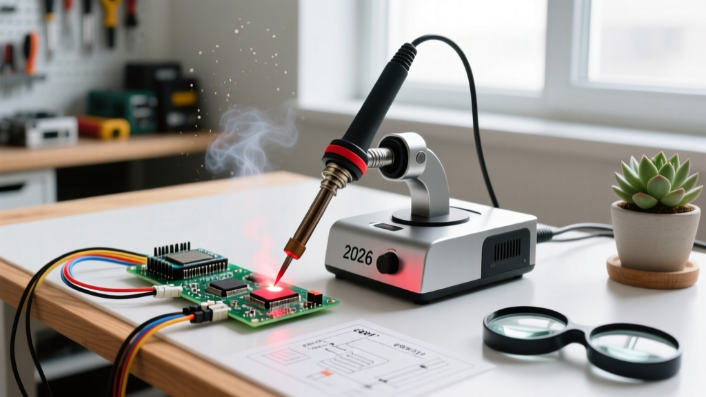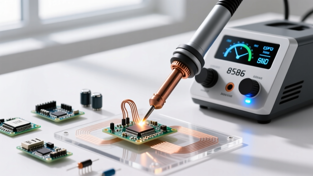

The 8586 SMD soldering station—frequently branded by manufacturers like Yihua, WEP, and Zenstyle—remains the undisputed champion of the budget electronics workbench in 2026. Priced between $45 and $65, this 2-in-1 hot air rework station and 60W soldering iron combo offers incredible utility for hobbyists and repair technicians. However, treating the 8586 like a professional-grade Hakko or Weller station out of the box is a fast track to lifted pads and blown components. To extract true precision from this budget tool, you must understand its thermal quirks, airflow mechanics, and electrical limitations.
The Out-of-the-Box Reality: Why You Must Calibrate
The most common failure mode for beginners using the 8586 SMD soldering station is trusting the digital LED display. Factory calibration on these budget units is notoriously inconsistent. The displayed temperature can easily drift 20°C to 40°C from the actual tip or nozzle temperature due to variance in the internal thermocouples and basic op-amp circuitry.
Trimpot Adjustment Procedure
Before attempting any fine-pitch SMD rework, you must calibrate both the iron and the hot air gun using a reliable K-type thermocouple multimeter (such as a Fluke or Brymen).
- Access the PCB: Unplug the station and remove the four screws on the bottom chassis to expose the main control board.
- Locate the Trimpots: Identify the two variable resistors (trimpots). Typically, VR1 controls the soldering iron offset, and VR2 controls the hot air gun offset. They are usually small blue or orange dials.
- Measure and Adjust: Place your K-type thermocouple directly against the soldering iron tip (use a tiny dab of thermal paste for accurate reading). Turn the station to 350°C. Using a ceramic flathead screwdriver, gently adjust VR1 until the digital display matches your multimeter's reading.
- Repeat for Hot Air: Suspend the thermocouple 10mm below the hot air nozzle. Set the gun to 350°C with airflow at dial 4. Adjust VR2 until the display matches the ambient air temperature reading.
Hot Air Thermodynamics and Airflow Profiles
The 8586 hot air gun features a 700W heating element and an 8-step airflow dial. The dial maps roughly to 15 through 120 Liters per minute (L/min). A critical mistake is using maximum airflow to "speed up" heating, which results in the convection effect blowing 0402 and 0603 passive components off the board. According to SparkFun's Hot Air Rework Guide, managing the thermal mass of the PCB requires balancing dwell time with moderate airflow.
8586 SMD Rework Profile Matrix
| SMD Package | Nozzle Size | Target Temp (Calibrated) | Airflow Dial | Est. Dwell Time |
|---|---|---|---|---|
| 0402 / 0603 Passives | Round 3mm | 320°C - 340°C | 2 - 3 (Low) | 3 - 5 Seconds |
| SOIC-8 / SOP-16 | Round 5mm | 350°C - 360°C | 4 - 5 (Medium) | 15 - 20 Seconds |
| QFP-48 / TQFP-64 | Round 8mm / Square | 360°C - 380°C | 5 - 6 (Med-High) | 30 - 45 Seconds |
| QFN with Thermal Pad | Round 6mm | 370°C (with PCB preheat) | 5 (Medium) | 40 - 60 Seconds |
Expert Warning: Never exceed 45 seconds of continuous hot air exposure on a single localized area without allowing the board to cool. Prolonged heat degrades the FR4 substrate's glass transition temperature (Tg), leading to internal delamination and pad lifting.
The Grounding Illusion: Fixing the 8586 ESD Flaw
While the 8586 SMD soldering station ships with a 3-prong power cable, internal teardowns frequently reveal that the earth ground pin is completely disconnected from the station's chassis and the soldering iron's tip grounding wire. When working on MOSFETs, CMOS logic, or raw microcontroller pins, electrostatic discharge (ESD) can instantly destroy silicon junctions. The ESD Association Fundamentals emphasize that proper grounding pathways are non-negotiable for sensitive electronics.
The 15-Minute Grounding Mod
- Open the chassis and locate the green/yellow earth wire from the IEC power inlet.
- Verify if it is actually soldered or screwed to the main transformer chassis or a dedicated ground bus on the PCB.
- If floating, solder a high-temperature silicone wire directly from the earth pin to the metal barrel of the soldering iron connector and to a dedicated 4mm banana jack mounted on the rear panel.
- Connect your ESD wrist strap and PCB grounding mat directly to this new banana jack, ensuring a true path to earth ground.
Soldering Iron Side: Beyond the Conical Tip
The 8586 utilizes the ubiquitous 900M series tip ecosystem. The factory-included 900M-B (conical) tip is practically useless for modern SMD work due to its abysmal thermal transfer rate on ground planes. To transform the iron side of the 8586 into a capable drag-soldering tool, you must invest in specific tip geometries:
- 900M-K (Knife Tip): The absolute best tip for drag soldering 0.5mm pitch TQFP and SOIC pins. The broad flat surface holds a molten solder wave, while the sharp point cleans up bridges.
- 900M-D24 (2.4mm Chisel): Ideal for general through-hole work and soldering larger SMD connectors where high thermal mass retention is required.
- 900M-IL (Micro Pencil): Necessary for 0402 rework and soldering tiny jumper wires on 0.2mm pitch BGA pads, though it requires careful temperature management to prevent oxidation.
Step-by-Step QFP-48 IC Removal and Replacement
Removing a high-pin-count Quad Flat Package (QFP) IC requires a synchronized dance between flux, heat, and mechanical extraction. Follow this exact sequence to avoid trace damage.
Phase 1: Preparation and Flux
Apply a generous amount of high-tack, no-clean tacky flux (such as Amtech NC-559-V2-TF) around all four sides of the IC. Do not skimp on flux; it acts as a thermal bridge, ensuring the heat from the hot air gun transfers evenly into the solder joints rather than just heating the plastic IC casing.
Phase 2: The Circular Heat Pattern
Set your calibrated 8586 hot air gun to 360°C with the airflow dial at 5. Using a 10mm round nozzle, hold the gun exactly 15mm above the IC. Move the nozzle in a continuous, steady circular motion over the chip. Never hold the gun stationary. Stationary heat will scorch the silicon die inside the package long before the center ground pads melt.
Phase 3: Extraction
After roughly 30 seconds, gently nudge the corner of the IC with fine-point titanium tweezers. If the chip slides freely on the molten solder surface tension, it is ready. Lift it straight up. If it resists, apply heat for another 10 seconds. Forcing a cold chip will rip the copper traces right off the fiberglass substrate.
Phase 4: Pad Cleanup and Replacement
Once the IC is removed, apply liquid flux and use a 2.0mm desoldering braid (wick) with your 8586 soldering iron (fitted with a 900M-D24 chisel tip at 350°C) to flatten the pads. Clean the area with 99% isopropyl alcohol. When placing the new IC, rely on the surface tension of freshly tinned pads and a small amount of flux to self-align the component before applying a final pass with the hot air gun to seat it permanently.
Final Thoughts on Budget Rework
The 8586 SMD soldering station is a masterclass in compromise. It lacks the rapid thermal recovery of a $400 JBC station and the sophisticated microprocessor airflow controls of a Quick 861DW. However, by manually calibrating the trimpots, respecting the thermal mass limits of FR4, and upgrading your tip selection, the 8586 becomes a remarkably capable tool for 95% of everyday PCB repair and prototyping tasks. Treat it with technical respect, and it will serve your workbench reliably for years.
For further reading on advanced soldering standards and defect identification, refer to the NASA Workmanship Standards for Electronic Assemblies, which provides exhaustive visual guides on acceptable solder joint geometries that apply regardless of the station price point.