
The Literal Answer: Maximum Temperature Thresholds
When electronics makers and assembly technicians ask, "how hot can a soldering iron get?", the literal answer depends entirely on the heater cartridge, the firmware limits, and the tool's intended application. Standard commercial soldering stations typically cap out between 850°F and 932°F (454°C to 500°C). However, specialized industrial irons and heavy-duty plumbing tools can exceed 1,000°F (537°C).
But reaching maximum temperature is rarely the goal. In precision PCB assembly, running an iron at its absolute thermal limit is a guaranteed way to destroy tip plating, carbonize flux, and lift SMD pads. To understand proper setup, we must first look at the hardware limits of the most popular stations on the market today.
Maximum Temperature & Wattage Matrix (2026 Models)
| Station Model | Max Temp Limit | Heater Wattage | Avg. Price Range |
|---|---|---|---|
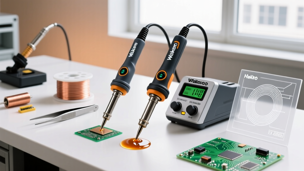
| Hakko FX-888D | 895°F (480°C) | 70W | $115 - $125 |
| Weller WE1010NA | 850°F (454°C) | 70W | $110 - $120 |
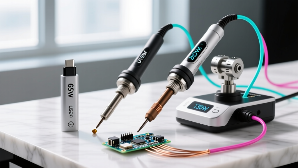
| Pinecil V2 (PD) | 932°F (500°C) | 65W (via USB-C PD) | $26 - $30 |
| JBC CD-2BQF | 842°F (450°C) | 130W | $600+ |
| Metcal CV-5200 | Fixed 575°F (302°C)* | 80W | $450 - $500 |
*Note: Metcal utilizes SmartHeat® induction technology. The tip contains a ferromagnetic core that loses its magnetic properties at the Curie point (e.g., 575°F), physically preventing the tip from exceeding that temperature regardless of how long it is left on.
Why "Hotter" Doesn't Mean "Faster" (Thermal Dynamics)
A common beginner mistake is cranking the temperature dial to 850°F+ when soldering large ground planes or thick wires, assuming higher heat equals faster melting. This fundamentally misunderstands the difference between temperature (an intensive property measuring average kinetic energy) and thermal mass/heat capacity (an extensive property measuring total stored energy).
The Thermal Mass Bottleneck
Imagine a 0.2mm micro-conical tip set to 900°F. It possesses high temperature but extremely low thermal mass. The moment it touches a large copper pour, the copper acts as a massive heatsink, instantly draining the tip's stored joules. The station's thermocouple detects the drop and fires the heater, but the 70W element cannot replenish the energy fast enough. The result? A cold joint, despite the iron's dial reading 900°F.
Conversely, a heavy 3.2mm chisel tip set to a moderate 650°F (343°C) holds vastly more thermal energy. It transfers heat into the joint efficiently without requiring extreme temperatures, preserving both the component and the tip.
The Oxidation Cliff
According to the Hakko USA Tip Care Guidelines, tip oxidation accelerates exponentially once the iron exceeds 400°C (752°F). At 850°F, the iron plating on the copper core dissolves into the solder at an alarming rate, leading to "de-wetting"—a failure mode where molten solder balls up and rolls off the tip rather than coating it. Once a tip de-wets, heat transfer plummets, and the tip is effectively ruined.
IPC Standards & Ideal Operating Ranges
Professional assembly environments do not guess their temperatures; they follow the IPC J-STD-001 requirements for soldered electrical and electronic assemblies. The ideal tip temperature is dictated by the solder alloy's liquidus (melting) point plus a thermal offset to account for joint mass and dwell time.
Rule of Thumb: Set your tip temperature 150°F to 200°F (65°C to 95°C) above the liquidus temperature of your solder alloy for standard through-hole and SMD work. For heavy thermal mass, increase tip geometry size before increasing temperature.
Alloy Temperature Cheat Sheet
- Sn63/Pb37 (Leaded Eutectic): Melts at 361°F (183°C). Ideal tip temp: 600°F - 650°F (315°C - 343°C).
- SAC305 (Lead-Free): Melts at 422°F (217°C). Ideal tip temp: 660°F - 715°F (350°C - 380°C).
- Sn96.5/Ag3.0/Cu0.5 (High-Reliability Lead-Free): Melts at 424°F (218°C). Ideal tip temp: 680°F - 730°F (360°C - 388°C).
- High-Temp Alloys (e.g., Sn10/Pb88/Ag2): Melts at 514°F (268°C). Ideal tip temp: 750°F+ (400°C+) — requires specialized high-wattage irons like the JBC CD-2BQF.
Step-by-Step: Calibrating Your Soldering Station
Out of the box, digital stations can have a temperature variance of ±10°F to ±20°F due to thermocouple placement inside the ceramic heater. For high-reliability work, or when transitioning to a new tip geometry, calibration is mandatory. Here is the professional calibration workflow using a K-type thermocouple tip thermometer (such as the Hakko 191 or Weller WSDH100, typically $130-$160).
- Prep the Sensor: Power on your tip thermometer. Apply a microscopic bead of high-temp thermal compound (or a tiny dab of eutectic solder) to the flat K-type sensor pad. This eliminates the air gap that causes false low readings.
- Set Baseline: Set your soldering station to 350°C (662°F) and allow it to stabilize for 3 minutes.
- Clean the Tip: Wipe the tip on a damp cellulose sponge or brass wool to remove oxidation. Do not use the tip while it is dry and oxidized.
- Measure: Press the flat face of the soldering tip squarely against the thermocouple sensor. Apply light, consistent downward pressure (about 1 lb of force).
- Wait for Equilibrium: Watch the thermometer display. It will spike, then slowly climb as the sensor heats up. Wait until the reading stabilizes for at least 5 seconds (usually takes 15-20 seconds total).
- Calculate Offset: If your station reads 350°C but the thermometer reads 342°C, you have a -8°C variance.
- Input Calibration: Enter your station's calibration mode. (On the Hakko FX-888D, hold the UP arrow while powering on; on the Pinecil V2, access the advanced settings menu via the OLED interface). Input the offset value to correct the internal PID controller.
Troubleshooting: When the Tip is Hot but the Joint is Cold
Even with perfect calibration, you will encounter joints that refuse to flow. Before touching the temperature dial, diagnose these common edge cases identified in Kester Technical Resources and field engineering reports:
- Flux Carbonization: If you leave a rosin-based flux on the tip at 700°F+ for more than a few seconds, it burns into a hard, black carbon shell. Carbon is a thermal insulator. Fix: Remove the iron from heat, let it drop to 500°F, and scrub vigorously with brass wool.
- Incorrect Tip Geometry: Trying to solder a 12AWG wire with a 1.0mm conical tip. The surface area contact is too small to transfer the necessary joules. Fix: Switch to a heavy bevel or wide chisel tip to maximize surface area contact.
- Thermal Relief Vias: PCB designers often use thermal relief spokes on ground planes, but sometimes a via connects directly to an internal copper layer, acting as a massive thermal vacuum. Fix: Pre-heat the PCB using a bottom-side hotplate (set to 120°C) to reduce the thermal delta the iron must overcome.
- Heater Degradation: In older ceramic heaters, the internal thermocouple wires can degrade, causing the station to "think" it is at 700°F when it is actually at 500°F. Fix: If calibration offset maxes out and the iron still fails to melt SAC305, replace the heater cartridge.
Final Takeaway: Respect the Alloy, Not the Dial
So, how hot can a soldering iron get? Up to 932°F on modern digital stations, and beyond 1,000°F on specialized tools. But in professional electronics work, the maximum temperature is a safety limit, not an operating target. By matching your tip geometry to the thermal mass of the joint, adhering to IPC liquidus offsets, and routinely calibrating your equipment with a K-type thermocouple, you will achieve flawless solder joints while extending the lifespan of your tips from weeks to months.