
Mastering Thermal Mass: The Hakko FX-601-02 Advantage
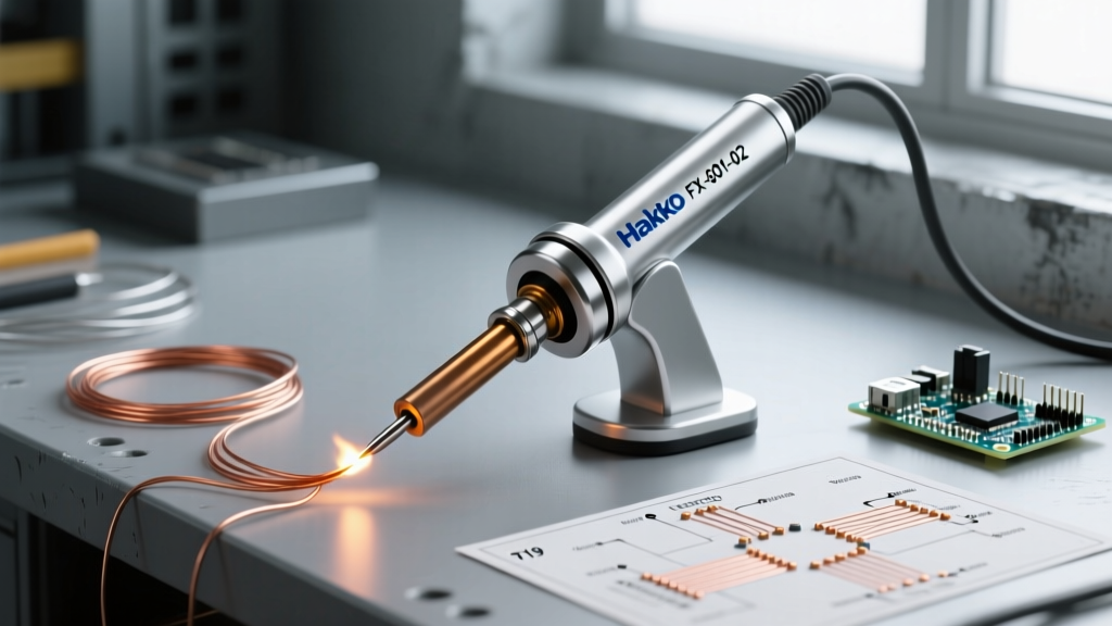
When tackling heavy-gauge wiring, large ground planes, or continuous copper foil work, standard 40W to 60W irons often suffer from severe thermal droop. This is where the Hakko FX-601-02 soldering iron with high heat capacity separates itself from the pack. Featuring a robust 67W ceramic heating element and a built-in temperature control dial, this tool is engineered for high thermal recovery. However, raw wattage is only half the equation. As a senior electronics technician, I have seen countless users misuse this iron by relying on extreme temperature settings rather than proper thermal transfer mechanics. In this expert guide, we break down the precise techniques, tip geometries, and maintenance protocols required to maximize the FX-601-02 in demanding 2026 DIY and professional environments.
The Anatomy of High Thermal Recovery
The FX-601-02 utilizes a 67W ceramic heater encased in a lightweight, ergonomic grip. Unlike older Nichrome wire wound elements, the ceramic core provides near-instantaneous thermal feedback. When the tip encounters a high-mass joint—such as a 10 AWG silicone wire or a multi-layer PCB ground pour—the sensor detects the temperature drop and drives maximum current to the heater.
According to Hakko USA, the FX-601 series can maintain stable temperatures even under continuous heavy-load conditions, provided the correct tip is mated to the joint. The critical mistake most hobbyists make is assuming a higher temperature dial setting compensates for a small tip. In reality, this leads to oxidized tips, burned flux, and delaminated PCB pads.
Optimal T19 Tip Selection for Heavy-Duty Joints
The FX-601-02 uses the T19 series tips, which feature a larger thermal mass than the standard T18 series. Selecting the right geometry is non-negotiable for high-capacity soldering. Below is a field-tested matrix for tip selection based on application.
| T19 Tip Model | Geometry | Primary Application | Thermal Transfer Rating |
|---|---|---|---|
| T19-D52 | Chisel (5.2mm) | 8 to 4 AWG wire, heavy battery tabs, large lugs | Excellent |
| T19-D24 | Chisel (2.4mm) | 12 to 16 AWG wire, thick PCB traces, XT60 connectors | Very Good |
| T19-BL | Conical R (3.2mm) | Stained glass copper foil, continuous bead soldering | Good (Directional) |
| T19-K | Knife | Drag soldering, tight clearance heavy-pins | Moderate |
Expert Rule: Always use the largest chisel tip that physically fits the joint. A 5.2mm chisel tip at 380°C (716°F) will transfer heat significantly faster and safer than a 1.6mm conical tip cranked to 480°C (896°F).
Temperature Profiling and Flux Activation
The FX-601-02 features a dial ranging from 240°C to 540°C (464°F to 1004°F). Understanding where to set this dial requires knowledge of flux chemistry and joint thermal mass.
The 380°C Sweet Spot
For 90% of heavy-duty electronics work (e.g., soldering 8 AWG to a 5mm bullet connector), set the dial to 380°C (716°F). This temperature is high enough to rapidly melt 63/37 Sn/Pb or SAC305 lead-free solder while allowing standard rosin-based (RMA) or no-clean fluxes to activate and clean the oxidation layer without instantly carbonizing. The IPC STD-001 guidelines emphasize that proper wetting is a function of adequate heat transfer over time, not extreme peak temperatures.
When to Push Past 450°C
Temperatures above 450°C (842°F) should be reserved exclusively for non-electronic, high-thermal-sink applications like stained glass leading or heavy copper plumbing lugs where flux burn-off is managed with external paste applications. Prolonged use at 540°C will destroy the iron plating on the T19 tip within hours.
Step-by-Step: Soldering 8 AWG to an XT90 Connector
To demonstrate the high heat capacity in action, here is a precise workflow for a common robotics and RC application.
- Preparation: Strip 8mm of insulation from the 8 AWG silicone wire. Apply a minimal amount of tack flux to the exposed copper strands.
- Iron Setup: Install the T19-D52 (5.2mm Chisel) tip. Set the FX-601-02 dial to 400°C (752°F) and allow 45 seconds for the ceramic element to fully saturate the tip's thermal mass.
- Pre-Tin the Wire: Apply 63/37 solder directly to the wire while stroking the chisel tip along the strands. The high wattage will melt the solder instantly, wicking it deep into the strands via capillary action.
- Pre-Tin the Connector: Hold the XT90 brass cup in a helping-hands fixture. Fill the cup 1/3 full of solder. Do not overfill.
- The Final Joint: Insert the pre-tinned wire into the brass cup. Apply the flat side of the T19-D52 tip to the side of the brass cup for exactly 2 to 3 seconds. The brass will rapidly reach the melting point of the internal solder, fusing the wire and cup into a single metallurgical bond.
- Cool Down: Remove the iron and hold the wire perfectly still for 4 seconds. Any movement during the plastic phase will cause a cold, disturbed joint.
Critical Warning: Thermal Shock
Never quench the FX-601-02 tip in a wet sponge or cold water to cool it down. The rapid temperature contraction will micro-fracture the internal ceramic heater element, leading to an open circuit. The replacement element (Hakko B5032) costs roughly $25, but the downtime is entirely avoidable.
Edge Cases and Failure Mode Prevention
Even the best tools fail if subjected to improper mechanical stress. The FX-601-02 is lightweight, which tempts users to apply excessive downward pressure when trying to force heat into a stubborn joint.
The Lateral Pressure Problem
The ceramic heater inside the handpiece is brittle. Pressing down at an angle or using the iron as a pry bar to lift components will snap the ceramic core. Heat transfer relies on surface area contact, not force. If the solder is not flowing, you have the wrong tip geometry or insufficient flux—not a need for more physical pressure.
Oxidation Management at High Temps
Operating continuously above 400°C accelerates tip oxidation. When the iron plating oxidizes, it turns black and repels molten solder (a phenomenon known as 'dewetting'). To combat this:
- Keep a brass wire sponge at your station. Brass is softer than the iron plating and removes oxidation without inducing thermal shock.
- Always leave a large blob of solder on the tip before placing the iron in its stand. This sacrificial solder layer oxidizes instead of the tip's iron plating.
- Use a tip tinner/reactivator (like Hakko FS-100) if dewetting occurs, rather than scraping the tip with a knife or sandpaper.
Market Position and Value in 2026
As of early 2026, the Hakko FX-601-02 retails between $85 and $105. Compared to entry-level variable-temperature irons that suffer from severe thermal lag, or high-end digital stations like the Hakko FX-951 that cost upwards of $350, the FX-601-02 occupies a unique middle ground. It provides 90% of the performance required for heavy-gauge automotive, marine, and robotics soldering at a fraction of the cost of a full benchtop station. Furthermore, the NASA Electronic Parts and Packaging (NEPP) Program frequently references the necessity of adequate thermal mass and proper tip wetting in hand-soldered high-reliability joints—principles that the FX-601-02 supports beautifully when wielded with technical discipline.
Final Verdict
The Hakko FX-601-02 is not a delicate tool for 0402 SMD components; it is a thermal workhorse. By respecting the physics of heat transfer, utilizing the T19 chisel geometries, and managing your temperature dial with precision, you can achieve flawless, high-reliability joints on the heaviest of thermal loads. Treat the ceramic element with care, manage your flux chemistry, and let the 67W high heat capacity do the heavy lifting.