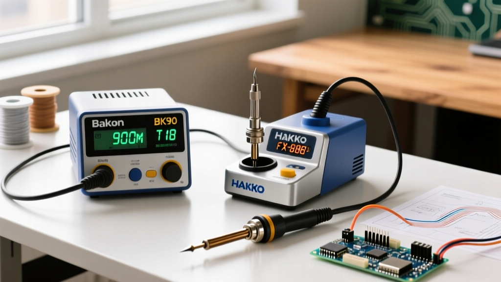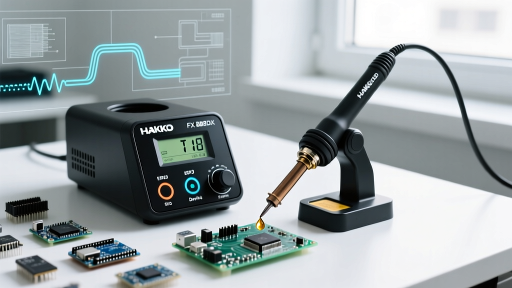

The Hakko FX 888DX soldering station remains the undisputed benchmark for professional and advanced DIY electronics workbenches in 2026. Replacing the legacy analog FX-888D, the DX model introduced digital push-button controls, a refined PID temperature control algorithm, and a 30% faster thermal recovery rate. Priced consistently around $115 to $125 USD, it offers a compelling entry point into precision soldering. However, out-of-the-box performance often falls short of its true potential due to factory temperature offsets and improper tip selection. As a senior technician, I frequently see users blame the station's 70W power envelope for cold solder joints, when the actual culprit is a lack of calibration and poor thermal mass management. This guide provides expert-level calibration procedures, advanced T18 tip selection strategies, and critical maintenance protocols to ensure your Hakko FX 888DX soldering station performs flawlessly on modern, high-density PCBs.
The 70W Thermal Envelope: Managing Ground Planes and Lead-Free Alloys
A common misconception in the electronics community is that 70W is insufficient for modern lead-free soldering or multi-layer boards with heavy ground planes. While it is true that 150W active-tip stations (like JBC or high-end Weller models) recover heat faster, the Hakko FX 888DX soldering station compensates through exceptional thermal mass transfer when paired with the correct T18 series tip. The secret lies in maximizing the surface area contact between the tip and the pad, rather than simply cranking the temperature to 400°C. Exceeding 380°C (716°F) with lead-free SAC305 alloys accelerates tip oxidation and violates the thermal excursion limits outlined in IPC industry standards, leading to pad delamination and compromised intermetallic compound (IMC) formation.
When soldering large vias or ground planes, the PID controller in the FX-888DX will detect the rapid heat sink effect and push the ceramic heater to its maximum duty cycle. If you are using a low-mass conical tip (like the T18-B), the tip temperature will plummet below the solder's liquidus point, resulting in a dull, grainy cold joint. By switching to a high-mass chisel or bevel tip, you provide a thermal reservoir that bridges the gap until the PID loop catches up.
Precision Offset Calibration Procedure
Out of the factory, the digital display on the FX-888DX may not perfectly match the actual temperature at the tip's working surface. Environmental factors, aging heating elements, and manufacturing tolerances can introduce an offset of up to ±15°C. To achieve the strict tolerances required by NASA-STD-8739.3 workmanship requirements, you must perform a manual offset calibration using a tip thermometer.
Required Tools for Calibration
- Hakko FG-100 Tip Thermometer (or an equivalent K-type thermocouple with a high-temperature surface probe capable of reading up to 480°C).
- SAC305 or 63/37 Leaded Solder Wire (to act as a thermal transfer medium between the probe and the tip).
- Brass Wool Sponge (Hakko 599B) for pre-calibration tip cleaning.
Step-by-Step Calibration Sequence
- Prepare the Tip: Clean the tip thoroughly using the brass wool. Apply a fresh coat of solder to the working surface to ensure optimal thermal transfer to the probe.
- Enter Calibration Mode: Power off the station. Press and hold the UP arrow button. While holding UP, power the station back on. The display will illuminate and show the current offset value (e.g., 000).
- Measure Actual Temperature: Set the station to 350°C (662°F) using the UP/DOWN buttons and press ENTER. Allow the station to stabilize for 60 seconds. Place the thermocouple probe into the molten solder pool on the tip and record the physical temperature.
- Adjust the Offset: If the physical thermometer reads 340°C while the display reads 350°C, you have a -10°C variance. Use the UP/DOWN arrows in the calibration menu to input an offset of +010. Conversely, if the probe reads 360°C, input -010.
- Save and Verify: Press and hold the ENTER button for 2 seconds to save the new offset. Power cycle the station, allow it to stabilize at 350°C again, and verify the probe reading matches the display within ±2°C.
T18 Tip Selection Matrix for Advanced PCB Work
The FX-888DX utilizes the T18 series tips, which slide over the B5031 ceramic heating element. Selecting the correct geometry is critical for thermal recovery. Below is an expert matrix for common 2026 PCB assembly scenarios.
| Tip Model | Geometry | Best Application | Thermal Mass |
|---|---|---|---|
| T18-D24 | Chisel (2.4mm) | Standard 0805/0603 SMD, DIP through-hole pins, general wire tinning. | Medium |
| T18-D32 | Chisel (3.2mm) | Heavy ground planes, large power connector lugs, thick gauge wires. | High |
| T18-C4 | Bevel (4.0mm) | Drag soldering fine-pitch QFP/QFN ICs, scooping excess solder. | High |
| T18-K | Knife | Vertical access in tight enclosures, precision spot soldering, rework. | Medium |
| T18-B2 | Conical (2.0mm) | 0402 components, micro-soldering, fine jumper wires. | Low |
Expert Warning: Avoid using conical tips (T18-B series) for general through-hole work. The minimal surface area contact drastically reduces heat transfer efficiency, forcing the FX-888DX to operate at maximum duty cycle and accelerating tip degradation.
Ceramic Heater Core (B5031) Preservation and Failure Modes
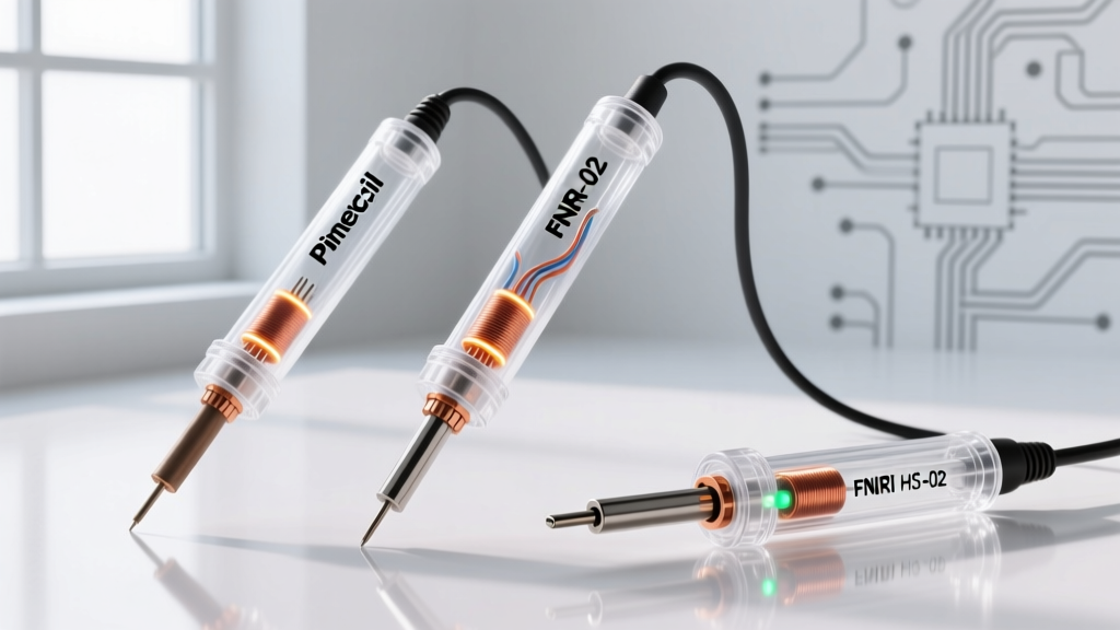
The handpiece of the Hakko FX 888DX soldering station (Model FX-8801) houses the B5031 ceramic heating element and sensor assembly. This component is highly efficient but mechanically fragile. The most common failure mode I encounter in repair shops is a fractured ceramic rod caused by improper tip extraction.
Over time, flux residue and oxidized solder can cause the T18 tip to seize onto the heater core. When users attempt to change the tip, they often twist or yank it with pliers, snapping the delicate sensor wire or cracking the ceramic housing. To prevent this, always apply a small amount of high-temperature anti-seize compound or fresh solder to the heater core shaft before installing a new tip. Furthermore, never use a wet cellulose sponge to clean the tip. The rapid thermal shock of dropping a 350°C tip onto a wet sponge causes micro-fractures in the ceramic and degrades the iron plating on the tip itself. Always use dry brass wool (Hakko 599B), which cleans the oxidation without dropping the tip temperature below the solder's melting point.
Troubleshooting Sensor Errors and Counterfeit Risks
If your FX-888DX display flashes an error code, it indicates a disruption in the thermocouple feedback loop:
- H20 Error (Sensor Short): Usually caused by solder bridging the internal contacts or a melted handpiece cord. Inspect the 5-pin DIN connector for debris.
- H21 Error (Sensor Open): The thermocouple circuit is broken. This almost always means the B5031 ceramic heater has reached the end of its lifespan or suffered physical impact damage. Replacement heaters cost approximately $25 USD and are easily swapped using a small Phillips screwdriver.
Finally, as of 2026, the market is flooded with counterfeit Hakko stations sold on third-party e-commerce platforms. These clones often feature poorly calibrated PID loops, ungrounded handpieces (posing a severe ESD risk to sensitive MOSFETs and microcontrollers), and substandard heating elements that fail within weeks. Always verify the official Hakko USA product listings and purchase only from authorized industrial distributors to ensure your station meets UL safety standards and provides the ESD-safe grounding required for modern electronics assembly.