
The Great Terminology Trap: Brazing vs. Silver-Bearing Soft Solder
If you are searching for instructions on how to silver solder with a soldering iron, we must first address a critical metallurgical misconception that ruins thousands of dollars in electronics equipment every year. In the jewelry, HVAC, and plumbing trades, "silver solder" refers to hard solder or brazing alloys (like Easy Flo 45) that contain 15% to 45% silver and require melting temperatures between 600°C and 800°C (1112°F to 1472°F). A standard electronics soldering iron maxes out around 450°C. It is physically impossible to melt true brazing silver solder with an iron.
However, in electronics manufacturing, "silver solder" refers to silver-bearing soft solders. These are tin-based alloys doped with 1% to 5% silver (such as Sn62 or SAC305) to improve joint strength, reduce tin leaching from component pads, and enhance thermal fatigue resistance. These alloys melt between 179°C and 220°C, making them perfectly suited for high-performance soldering irons. This guide focuses exclusively on the technique, thermal management, and tooling required to master silver-bearing soft solders in 2026.
Alloy Comparison Matrix: Choosing Your Silver Solder
Selecting the correct silver-bearing alloy dictates your iron temperature, flux requirements, and dwell time. Below is a breakdown of the most common silver-bearing alloys used in modern electronics and heavy-duty prototyping.
| Alloy Designation | Composition | Melting Point | Primary Use Case | Iron Temp Setting |
|---|---|---|---|---|
| Sn62/Pb36/Ag2 | 62% Sn, 36% Pb, 2% Ag | 179°C (354°F) | Leaded silver-bearing; prevents silver pad leaching in RF/microwave boards. | 300°C - 320°C |
| SAC305 | 96.5% Sn, 3.0% Ag, 0.5% Cu | 217°C - 220°C | Standard RoHS-compliant lead-free silver alloy for commercial electronics. | 340°C - 360°C |
| Sn95/Ag5 | 95% Sn, 5% Ag | 221°C - 245°C | High-reliability plumbing, high-temp electronics, and die-attach. | 360°C - 380°C |
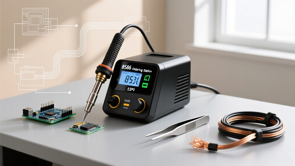
Selecting the Right Soldering Station for Silver Alloys
Silver-bearing alloys—particularly lead-free variants like SAC305—have notoriously poor wetting characteristics and higher surface tension compared to standard 63/37 tin-lead. To compensate, you need a soldering station with exceptional thermal recovery, not just a high maximum temperature.
- Heavy-Duty / High-Reliability (JBC CD-2BQF): Priced around $650 in 2026, JBC's cartridge-based system heats the tip from the inside out. The C245 series tips offer unmatched thermal transfer for silver-bearing alloys on heavy ground planes.
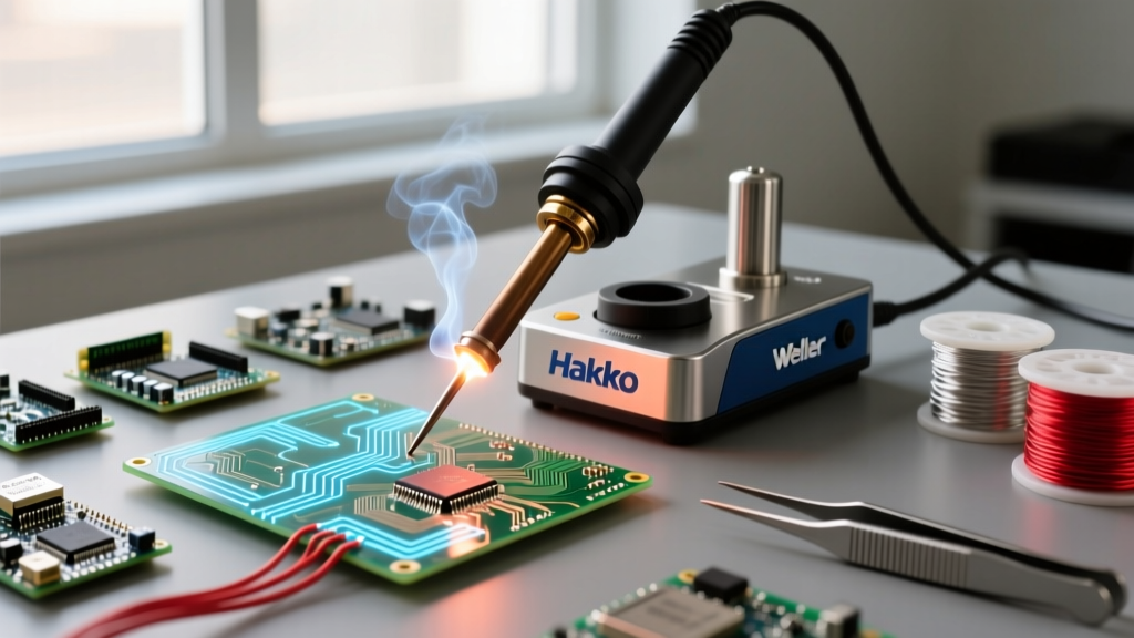
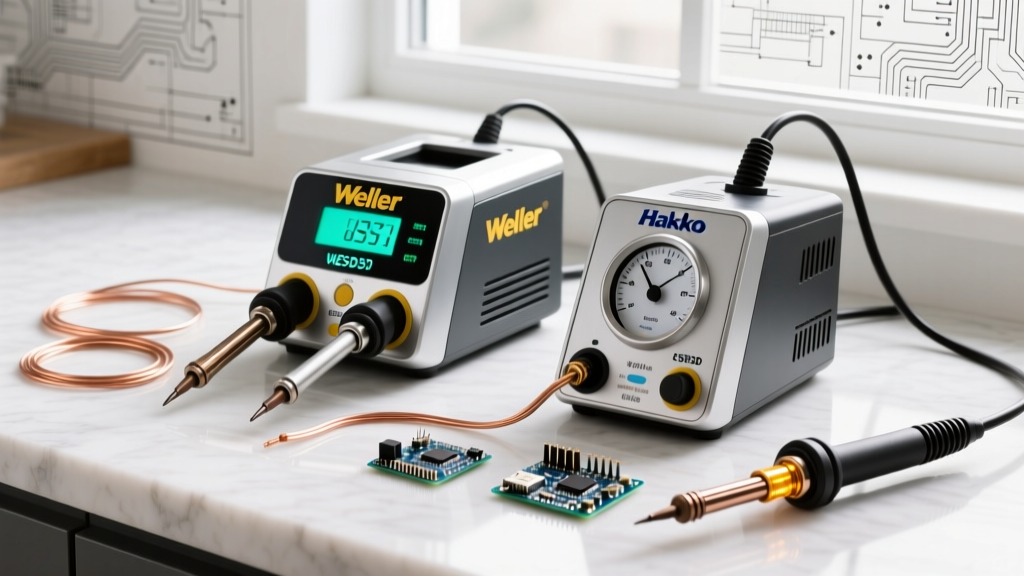
- Professional Production (Hakko FX-951): At approximately $330, this station uses T18 composite tips where the heating element is embedded directly into the tip. It handles SAC305 effortlessly without scorching flux.
- Prosumer / Advanced Hobbyist (Weller WE1010NA): Coming in at $140, the WE1010 is a capable 70W station. However, when using silver-bearing alloys, you must upgrade to the larger ETA chisel tips to maximize surface area and thermal mass.
Expert Insight: Never compensate for poor thermal recovery by cranking your iron to 400°C+. High heat oxidizes silver-bearing solder instantly, creating a dull, grainy, and brittle intermetallic compound (IMC) layer. Keep the temperature under 360°C and rely on a larger tip profile instead.
Step-by-Step Technique Guide for Silver-Bearing Alloys
Working with silver-doped solder requires strict adherence to IPC J-STD-001 workmanship standards, particularly regarding flux activation and dwell time. Follow this precise workflow for optimal wetting.
1. Flux Application is Non-Negotiable
Silver alloys oxidize rapidly at melting temperatures. You must use a high-activity flux. For general electronics, a No-Clean flux like Kester 245 or Indium NC-256-TAC (approx. $15 per pen) is ideal. Apply the flux to the pad and lead before the iron touches the joint.
2. The 'Sacrificial Tinning' Method
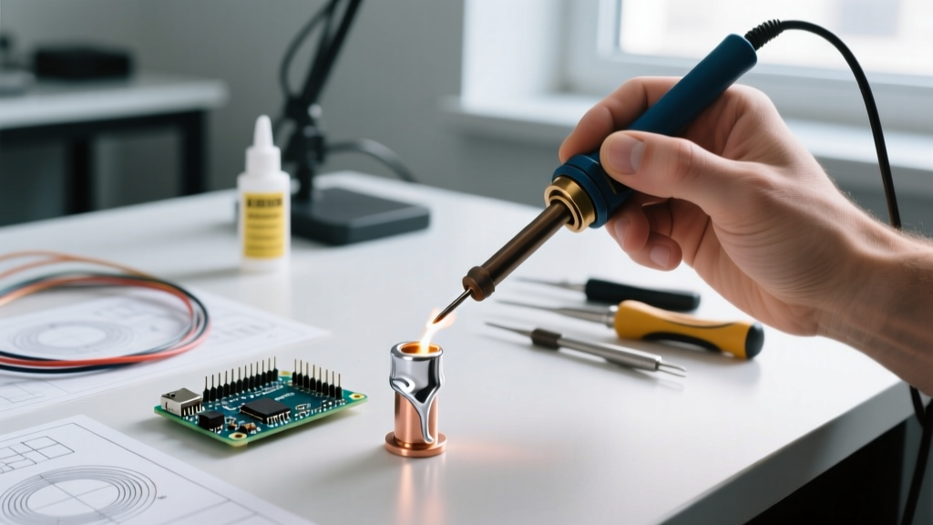
Silver in the molten solder can actually leach the iron plating off your soldering tip if the tip is left bare at high temperatures. To prevent this, always melt a tiny amount of standard Sn63/Pb37 (or Sn99/Cu1) onto the tip first. This sacrificial layer protects the tip's iron plating before you introduce the silver-bearing wire to the joint.
3. Thermal Transfer and Dwell Time
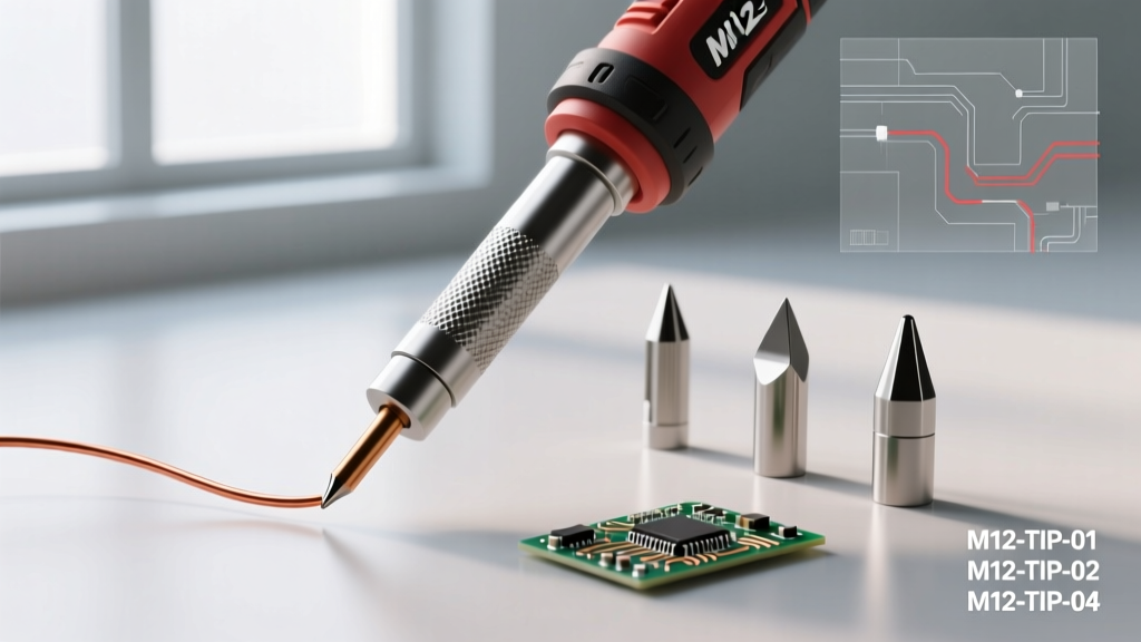
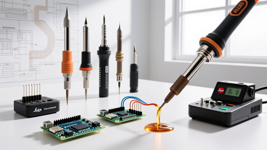
- Place the tinned chisel tip (e.g., Hakko T18-D24 or JBC C245-945) so it bridges the component lead and the PCB pad simultaneously.
- Hold for exactly 1.5 to 2.5 seconds to allow the flux to boil and the metals to reach the liquidus temperature.
- Feed the silver-bearing solder wire into the joint, not the iron tip. Capillary action will draw the molten alloy through the via or around the lead.
- Remove the solder wire first, then remove the iron at a 45-degree angle to encourage a smooth fillet.
Preventing Silver Leaching and Tip Degradation
One of the most common failure modes when technicians attempt to silver solder with a soldering iron is rapid tip degradation. According to Hakko's official tip care guidelines, leaving a soldering iron idle at 360°C+ with silver-bearing solder on the tip causes the silver to dissolve the protective iron plating, exposing the copper core to rapid oxidation.
Prevention Protocol:
- Utilize your station's auto-sleep feature. Set the standby temperature to 150°C if the iron will be idle for more than 2 minutes.
- Never wipe the tip completely dry on a brass sponge before placing it in the holder. Always leave a generous blob of standard tin-lead or tin-copper solder on the tip as a protective barrier against the silver alloy.
- Use a damp cellulose sponge (distilled water only) for wiping, as tap water minerals can cause micro-pitting on the iron plating over time.
Troubleshooting Common Failure Modes
Even with the right equipment, silver-bearing alloys can present unique visual and structural anomalies. Here is how to diagnose them based on NASA's Electronic Parts and Packaging (NEPP) soldering standards.
Dull or Grainy Joint Appearance
Cause: Unlike tin-lead solder, SAC305 silver solder naturally cures with a slightly duller, more satin finish. However, a distinctly grainy or cracked surface indicates a disturbed joint. The component moved while the silver alloy was passing through its plastic (semi-solid) state during cooling.
Fix: Secure the component with Kapton tape or a PCB fixture. Do not blow compressed air on the joint to cool it faster; allow it to solidify naturally for 3-4 seconds.
Dewetting (Solder Pulling Away from the Pad)
Cause: The silver alloy has oxidized, or the pad's OSP (Organic Solderability Preservative) coating has burned away before the solder could wet the copper.
Fix: Clean the pad with isopropyl alcohol, apply a generous amount of water-soluble flux, and pre-tin the pad with a standard leaded alloy before attempting to flow the silver-bearing solder over it.
Excessive Intermetallic Compound (IMC) Growth
Cause: Dwell times exceeding 4 seconds. Silver accelerates IMC formation when exposed to prolonged heat, creating a brittle glass-like layer that will fracture under mechanical or thermal stress.
Fix: Increase your iron's tip size to transfer heat faster, reducing the required dwell time to under 3 seconds.
Final Thoughts on Silver-Bearing Techniques
Mastering how to silver solder with a soldering iron is less about brute-force heat and entirely about metallurgical discipline. By understanding the exact melting profiles of alloys like SAC305 and Sn62, utilizing high-thermal-recovery stations from brands like JBC or Hakko, and strictly managing your flux and dwell times, you can achieve aerospace-grade, high-reliability joints. For further reading on advanced alloy behaviors and lead-free transition challenges, consult the technical resources available at Indium Corporation's solder alloy database.