
The Evolution of the Electronic Soldering Gun
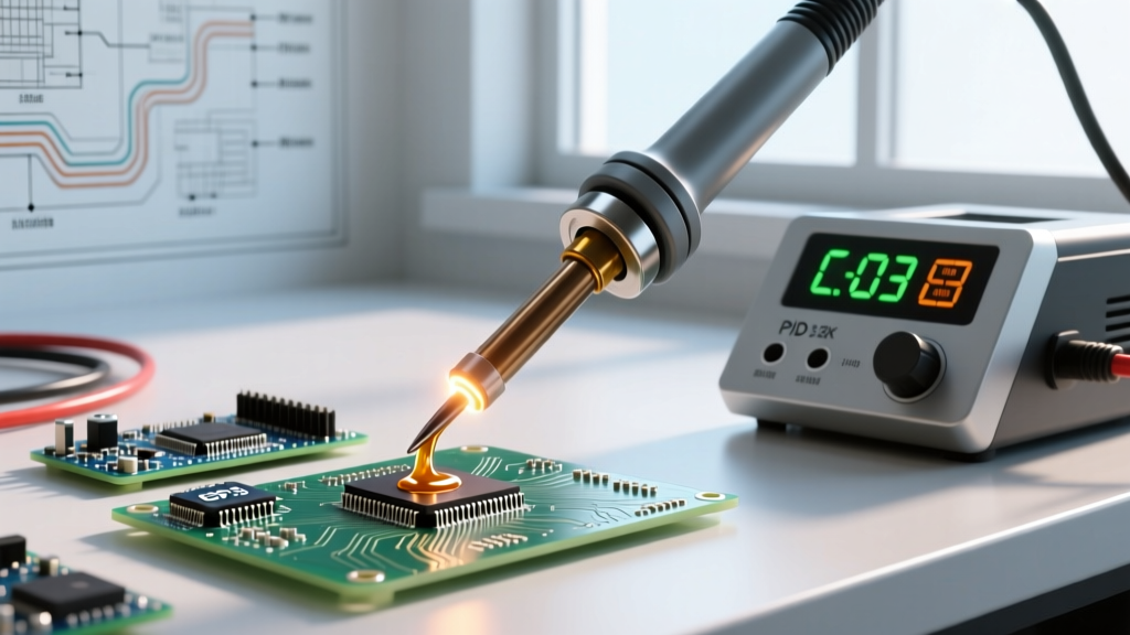
In the past, the term 'soldering gun' almost exclusively referred to a heavy, 60Hz transformer-based tool like the classic Weller D550. While these tools were exceptional for plumbing, automotive harnesses, and heavy lug terminals, their stray magnetic fields and massive thermal overshoot made them a nightmare for delicate printed circuit boards (PCBs). Fast forward to 2026, and the modern electronic soldering gun has been fundamentally redefined. Today's professional tools utilize high-frequency induction heating or digitally controlled solid-state triggers to deliver 100W to 200W of instantaneous thermal recovery without the destructive magnetic loops of their ancestors.
For professionals tackling high-current power supplies, EV battery management systems (BMS), and heavy-gauge wire harnesses, mastering the electronic soldering gun is non-negotiable. This guide provides expert-level techniques for managing thermal mass, selecting the right metallurgy, and avoiding catastrophic component damage when working on demanding electronic assemblies.
The Thermal Mass Dilemma in Modern Electronics
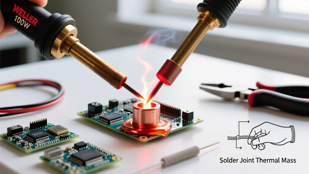
When soldering an 8 AWG or 10 AWG wire to a multi-layer PCB ground plane, standard 40W to 60W pencil irons simply fail. The internal copper planes act as a massive heat sink, wicking thermal energy away from the joint faster than a standard ceramic heater can replenish it. The result? Cold solder joints, excessive dwell time, and delaminated copper pads. According to the IPC J-STD-001 standard, excessive dwell time can compromise the intermetallic compound (IMC) layer, leading to brittle joints that fail under mechanical vibration or thermal cycling.
Tool Matrix: Transformer vs. Modern Electronic Guns
Understanding the difference between legacy tools and modern electronic variants is critical for selecting the right equipment for your workbench.
| Feature | Classic Transformer Gun | Modern Electronic Trigger Gun | Standard Digital Station |
|---|---|---|---|
| Wattage Output | 100W - 250W (Peak) | 80W - 150W (Continuous/Smart) | 40W - 80W |
| Heating Element | Copper secondary loop | High-Frequency Induction / Solid State | Ceramic Cartridge |
| Magnetic Emission | High (Stray 60Hz field) | Shielded / Negligible | None |
| Thermal Recovery | Slow (Transformer lag) | Instant (Under 2 seconds) | Fast (3 - 5 seconds) |
| Best Application | Lug terminals, plumbing | BMS, Heavy PCB, 10 AWG wire | SMD, ICs, 22 AWG wire |
| Typical 2026 Cost | $50 - $90 | $180 - $350 | $120 - $250 |
Step-by-Step: Soldering High-Current Joints Safely
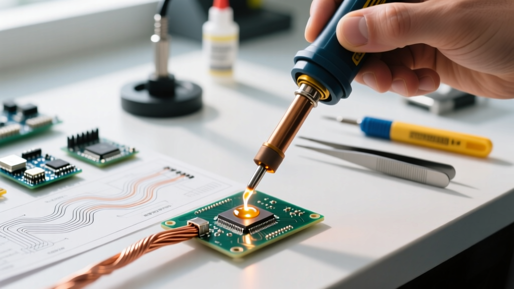
To achieve a Class 3 compliant joint on a heavy-duty power connector, you must manage both the wire and the PCB pad simultaneously. Here is the expert workflow for utilizing a modern electronic soldering gun.
1. Mechanical Preparation and Pre-Tinning
Never attempt to solder a bare, stranded 10 AWG wire directly to a PCB. Strip exactly 6mm to 8mm of insulation. Apply a high-activity, no-clean flux like Kester 951 or Amtech NC-559-V2-TF. Pre-tin the wire using a sacrificial iron or the electronic gun on a lower power setting until the solder wicks fully into the strands, leaving no dry copper visible.
2. The 'Heat and Feed' Trigger Technique
Modern electronic soldering guns often feature a two-stage trigger. The first stage engages a baseline temperature (e.g., 300°C), while the second stage pushes the tool to maximum output (e.g., 380°C) for heavy thermal loads.
- Apply the primary bevel of the tip to the PCB pad, not the wire. The pad requires more time to reach reflow temperature due to internal ground plane connections.
- Squeeze the trigger to the first stage. Hold for 1.5 seconds to allow the pad to absorb heat.
- Depress the second stage and simultaneously introduce the pre-tinned wire to the opposite side of the pad.
- Feed 63/37 (Sn63Pb37) or SAC305 lead-free solder directly into the intersection of the wire and pad, never directly onto the iron tip.
- Release the trigger fully the moment the solder flows smoothly into the via or pad. Total dwell time should not exceed 3 to 4 seconds.
Flux Chemistry Under Extreme Thermal Stress
When an electronic soldering gun transfers 150W of energy into a joint, the localized temperature spike can instantly vaporize standard mild fluxes, leaving behind a burnt, sticky residue that fails to clean the oxidation layer. For high-thermal-mass joints, you need a flux with a high activation temperature and a slow boil-off rate.
- RA (Rosin Activated) Flux: Ideal for heavily oxidized thick wires. The halide activators strip tough oxides but require post-soldering cleaning with isopropyl alcohol or a dedicated PCB wash to prevent long-term dendritic growth.
- No-Clean Tacky Flux: The industry standard for BMS and power supply rework. Its high viscosity prevents it from boiling away instantly when the soldering gun touches the pad, maintaining a protective envelope over the molten solder.
- Water-Soluble Flux: Avoid using water-soluble fluxes with high-wattage electronic guns. The rapid thermal spike can cause the flux to splatter, creating microscopic corrosive droplets that migrate under nearby BGA packages or QFN chips.
Navigating Lead-Free (SAC305) vs. Leaded (Sn63) Alloys
The choice of solder alloy drastically changes how you wield an electronic soldering gun. Sn63Pb37 (leaded) melts at a eutectic 183°C, meaning it transitions from solid to liquid instantly. This provides a clear visual cue and a wide plastic working window.
Conversely, SAC305 (lead-free) melts at 217°C to 220°C and exhibits a pasty phase transition. When using a soldering gun on SAC305, you must hold the tool in place for an additional 0.5 to 1.0 seconds after the solder appears molten to ensure the internal thermal mass of the wire has actually reached the liquidus temperature. Disturbing a SAC305 joint during its pasty cooling phase will result in a disturbed joint, characterized by a dull, grainy appearance and severe structural weakness.
The Hidden Danger: Stray Magnetic Fields and Hall Sensors
Expert Warning: Never use a legacy 60Hz transformer-based soldering gun near Hall-effect sensors, unshielded inductors, or sensitive CMOS logic gates. The alternating magnetic field generated by the transformer's secondary loop can induce parasitic voltages, permanently latching or destroying silicon junctions. Always verify your tool utilizes shielded high-frequency induction or solid-state electronic control before working on mixed-signal PCBs. For more on soldering safety and ESD precautions, refer to the Electronics Notes guide on soldering equipment.
Tip Selection: Why the Bevel Bucket Wins
For heavy electronic joints, the standard 1.6mm chisel tip is practically useless. It lacks the thermal mass to transfer energy into a 10 AWG wire, and the flux will carbonize on the flat surface before the joint reaches reflow temperature.
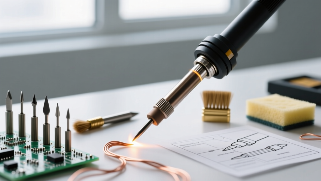
Expert technicians rely on the 'bevel bucket' (or concave bevel) tip, typically 4mm to 6mm in diameter. The concave shape cradles the round wire, maximizing the surface area contact by up to 40% compared to a flat chisel. Furthermore, the bucket holds a small reservoir of molten solder and flux, creating a localized thermal bridge that accelerates heat transfer and reduces overall dwell time.
Maintenance and Preventing Copper Core Dissolution
Operating an electronic soldering gun at 400°C for extended periods accelerates tip erosion, specifically the dissolution of the iron plating by the tin in the solder alloy. To maximize the lifespan of your replacement tips:
- Never leave the gun idle at max temperature. Utilize the tool's auto-sleep feature to drop the temperature to 150°C after 5 minutes of inactivity.
- Use brass wool, not a wet sponge. A wet sponge causes rapid thermal shock, leading to micro-fractures in the iron plating and eventual core exposure.
- Re-tin before holstering. Always apply a thick layer of cheap, heavily fluxed rosin-core solder or a dedicated tip tinner (like Hakko 599B) to the tip before turning the tool off. This sacrificial layer prevents oxidation while the tip cools.
Final Thoughts on Precision Power
The electronic soldering gun bridges the gap between the brute force of plumbing tools and the precision of micro-soldering stations. By understanding the thermal dynamics of heavy PCB joints, utilizing the two-stage trigger effectively, and respecting the metallurgical limits of your tips, you can achieve flawless, high-reliability connections on the most demanding power electronics projects. For further reading on advanced tool calibration and firmware updates for digital stations, consult the Weller Tools knowledge base for specific cartridge compatibility charts and thermal profiling guides.