
The Core Rule: Melting Point vs. Working Temperature
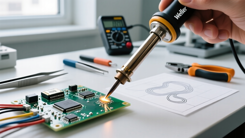
When makers and electronics engineers ask, "how hot should my soldering iron be?", the most common mistake is setting the station dial to the exact melting point of the solder alloy. This guarantees failure. Soldering is fundamentally an exercise in thermal transfer, not just melting. To achieve a reliable metallurgical bond, your soldering iron tip must supply enough thermal energy to heat the component lead, the PCB pad, and the flux core simultaneously.
According to the IPC J-STD-001 standard for soldered electrical and electronic assemblies, the working temperature of the iron must be significantly higher than the liquidus temperature of the alloy to ensure proper wetting and flux activation. As a baseline engineering rule, your station should be set 40°C to 60°C (72°F to 108°F) above the solder's melting point for standard through-hole and SMD work, and up to 80°C higher for heavy ground planes.
Solder Alloy Temperature Matrix
The exact temperature you need depends entirely on the chemical composition of your solder wire. In 2026, the industry remains split between traditional leaded eutectic alloys for hobbyist/repair work and lead-free SAC alloys for commercial manufacturing. Refer to the matrix below for precise baseline settings.
| Alloy Type | Composition | Melting Point | Ideal Station Setting | Primary Use Case |
|---|---|---|---|---|
| Leaded Eutectic | Sn63/Pb37 | 183°C (361°F) | 300°C - 320°C (570°F - 625°F) | Hobbyist, repair, vintage audio |
| Lead-Free SAC305 | Sn96.5/Ag3.0/Cu0.5 | 217°C (430°F) | 340°C - 360°C (645°F - 680°F) | Commercial SMD, modern PCBs |
| Lead-Free High-Temp | Sn99.3/Cu0.7 | 227°C (440°F) | 350°C - 380°C (660°F - 715°F) | Plumbing, heavy wire tinning |
| Low-Temp Bismuth | Sn42/Bi58 | 138°C (280°F) | 200°C - 220°C (390°F - 425°F) | Thermal-sensitive components |
Step-by-Step Calibration Guide for Digital Stations
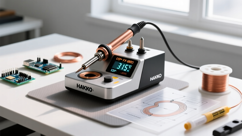
Even high-end stations like the Hakko FX-888D or Weller WE1010NA can drift from their factory calibration due to thermocouple aging and tip oxidation. If your solder balls up and refuses to wet the pad, your station might be reading 340°C while the physical tip is only outputting 290°C. Here is how to properly calibrate your equipment using a tip thermometer.
Required Tools
- Tip Thermometer: Hakko FG-100B or Weller WSD-4 (approx. $120-$150).
- Sacrificial Solder: Fresh Sn63/Pb37 wire with a rosin core (e.g., Kester 245).
- Brass Wire Sponge & Damp Cellulose Sponge.
The Calibration Procedure
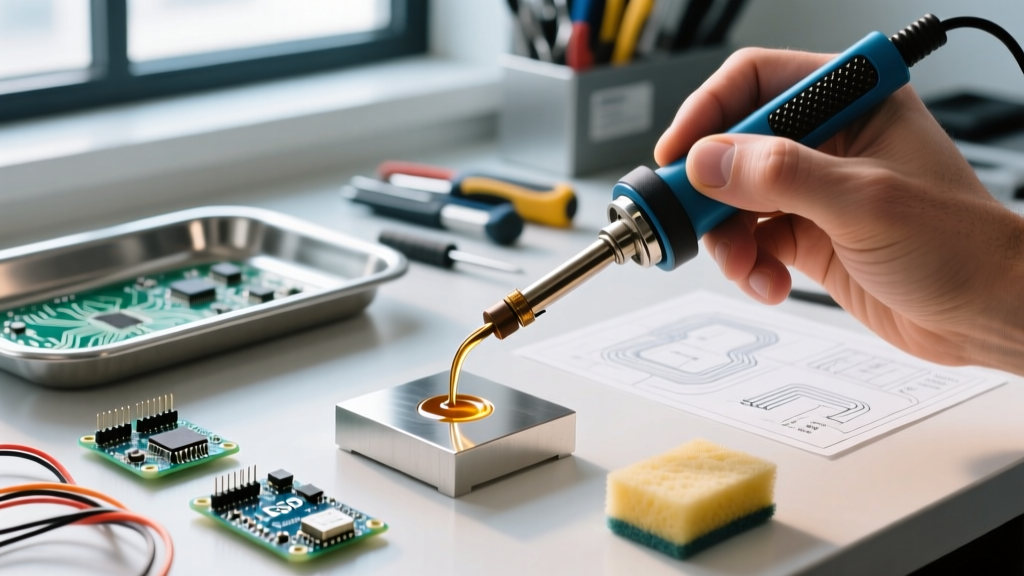
- Prep the Tip: Turn your station to 300°C. Once heated, heavily tin the tip with fresh solder to ensure maximum thermal conductivity.
- Prepare the Sensor: Coil the thermocouple wire of your FG-100B into a tight, flat spiral. Apply a small drop of fresh solder to the center of the coil.
- Measure Baseline: Press the tinned soldering iron tip directly onto the solder drop on the thermocouple. The flux will activate, creating a liquid solder bridge between the tip and the sensor.
- Wait for Stabilization: Hold the iron perfectly still for 10-15 seconds. Wait for the digital readout on the thermometer to stop climbing and stabilize.
- Calculate Offset: If your station is set to 300°C, but the FG-100B reads 285°C, you have a -15°C offset. Access your station's calibration menu (on the FX-888D, hold the UP arrow while turning it on, navigate to the offset menu) and add +15°C to the internal PID controller.
- Verify: Clean the tip, re-tin, and repeat the measurement to confirm the physical tip temperature now matches the digital display.
Adjusting for Thermal Mass: When to Break the Rules
A frequent point of frustration occurs when soldering large ground planes or heavy-gauge wires (10 AWG and thicker). The iron touches the pad, the solder melts for a fraction of a second, and then the joint instantly freezes into a dull, grainy mess. This is a thermal mass failure, not a melting point failure.
The copper pour of a ground plane acts as a massive heatsink, pulling thermal energy away from the tip faster than the station's heating element can replenish it. The amateur response is to crank the station dial up to 400°C (750°F). Do not do this.
Expert Warning: Running a standard chisel tip at 400°C+ will instantly burn off the rosin flux, causing the tip to oxidize and turn black within minutes. This permanently destroys the iron plating, leading to the dreaded 'black tip' syndrome where solder simply rolls off the iron. For extreme thermal mass, rely on geometry and wattage, not extreme heat. Refer to the Hakko Official Tip Care Guide for detailed oxidation prevention protocols.
The Correct Engineering Solution
- Increase Tip Surface Area: Switch from a standard 2.4mm chisel (e.g., Hakko T18-D24) to a wide bevel or a massive 5.2mm chisel (T18-D52). More surface area equals faster thermal transfer without raising the temperature.
- Upgrade Station Wattage: If you are using a 65W station (like the Pinecil V2 or TS100) and hitting thermal limits on multi-layer PCBs, upgrade to a 75W+ active-tip station like the JBC CD-2BQE or Weller WXD2. These stations detect the thermal drop instantly and dump maximum current into the heater cartridge.
- Preheat the PCB: Use a bottom-side PCB preheater set to 120°C to reduce the thermal delta between the iron and the board.
The Science of the Intermetallic Compound (IMC) Layer
Understanding how hot your iron should be requires understanding what happens at the microscopic level. When molten tin contacts a copper pad, they react to form an Intermetallic Compound (IMC) layer, primarily Cu6Sn5. This layer is the actual physical bond holding your component to the board.
The formation of the IMC layer is dependent on both temperature and time. According to research published by the NASA Electronic Parts and Packaging (NEPP) Program, the ideal IMC thickness is between 1 to 3 micrometers.
- Too Cold / Too Fast: The IMC layer fails to form properly. The solder merely sits on top of the copper like water on wax. This results in a 'cold joint', which is mechanically weak and prone to high electrical resistance.
- Too Hot / Too Slow: If you leave a 380°C iron on a pad for 5+ seconds, the Cu6Sn5 converts into Cu3Sn. This secondary layer is highly brittle and prone to micro-fracturing under thermal cycling or mechanical vibration. Furthermore, excessive heat causes the PCB's FR4 resin to delaminate and the copper pad to lift off the board entirely.
Therefore, the 'perfect' temperature is the lowest possible setting that allows you to complete the solder joint in 1.5 to 3.0 seconds. If it takes longer than 3 seconds, your iron is either set too low, or your tip geometry is too small for the pad's thermal mass.
Troubleshooting Common Temperature Symptoms
Before you adjust your station's dial, diagnose the physical symptoms of your solder joints to determine if a temperature change is actually required.
1. Solder Balls Up and Refuses to Wet
Diagnosis: The tip is too cold, OR the tip is oxidized. Fix: First, clean the tip on brass wool and apply fresh flux-core solder. If it still balls up, increase the station temperature by 15°C. If the problem persists, the tip's iron plating is compromised and must be replaced.
2. Flux Burns and Smokes Instantly
Diagnosis: The iron is too hot for the specific flux chemistry. Standard rosin (RMA) flux activates around 180°C and burns off rapidly above 350°C. Fix: Drop the temperature by 20°C. If you require high heat for lead-free SAC305, switch to a synthetic no-clean flux chemistry designed for high-temperature profiles.
3. Dull, Grainy, or Frosty Joints
Diagnosis: Disturbance during cooling, or a cold joint caused by insufficient thermal transfer. Note that lead-free SAC305 joints naturally appear slightly duller than shiny leaded joints, but they should never be grainy. Fix: Ensure the component is held perfectly still until the solder fully solidifies. If the joint remains grainy, increase your tip size to transfer heat into the component lead faster.
Smart Irons and PID Tuning in 2026
Modern smart irons like the Pinecil V2 and MHP50 utilize advanced PID (Proportional-Integral-Derivative) control algorithms. Unlike older analog stations that overshoot and undershoot the target temperature, PID controllers calculate the rate of heat loss and adjust power delivery microsecond-by-millisecond. If you are using a Pinecil V2, you can access the advanced settings menu to tweak the PID values. For heavy copper pours, slightly increasing the 'P' (Proportional) value allows the iron to dump more wattage the millisecond it detects a temperature drop upon touching the board, effectively mimicking the performance of much more expensive JBC stations.
Final Calibration Takeaways
There is no single universal temperature for soldering. The answer to 'how hot should my soldering iron be' is always a dynamic calculation based on your alloy's melting point, the thermal mass of your target joint, and the activation temperature of your flux. Start at the baseline matrix provided above, calibrate your station's physical offset every six months, and let the 3-second rule guide your real-world adjustments. By respecting the metallurgy of the IMC layer and avoiding the trap of excessive heat, you will produce joints that are both mechanically robust and electrically flawless.