
Why Build Your Own Soldering Station?
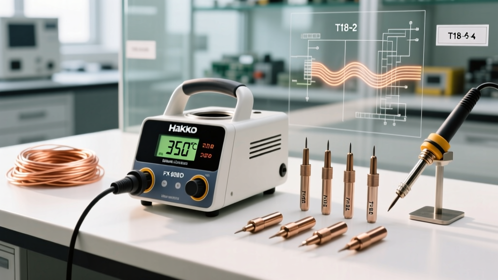
In 2026, commercial soldering stations like the Hakko FX-888D or Weller WE1010 remain industry standards, but their retail prices often hover between $120 and $160. For beginners, hobbyists, and electronics students, building a custom station is not just a massive cost-saver—it is a masterclass in power electronics, thermal dynamics, and circuit safety. By understanding a DIY soldering iron wiring diagram, you transition from merely using tools to engineering them.
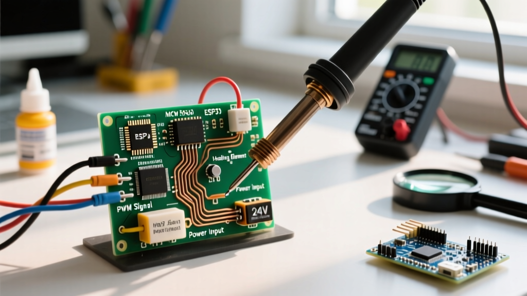
This beginner guide focuses on constructing an open-loop 24V DC PWM (Pulse Width Modulation) soldering station. Unlike closed-loop systems that use microcontrollers and thermocouple feedback to maintain an exact temperature, an open-loop system uses a manual duty cycle dial to regulate average power delivery. It is the safest, most straightforward entry point into DIY soldering station design.
Core Architecture: Open-Loop PWM Explained
Before grabbing your wire strippers, you must understand the physics governing your build. Pulse Width Modulation controls the average power delivered to the heating element by rapidly switching the DC voltage on and off. If you set your PWM controller to 50%, the 24V power supply is delivering full voltage to the ceramic heater half the time, and zero voltage the other half. Because the thermal mass of the iron tip acts as a low-pass filter, it smooths these electrical pulses into a steady, continuous heat output.
Expert Insight: According to SparkFun's Guide to Pulse Width Modulation, PWM is vastly more efficient than linear voltage regulation (like using a potentiometer to drop voltage). A linear resistor would dissipate the unused energy as wasted heat, whereas a PWM MOSFET switch operates at near 100% efficiency, keeping your controller cool.
Bill of Materials (BOM) & Sourcing
To ensure your DIY soldering iron wiring diagram functions safely, you must source components that can handle continuous thermal and electrical loads. Below is the recommended 2026 parts list.
| Component | Specification | Est. Cost (2026) | Function |
|---|---|---|---|
| DC Power Supply | 24V 5A (120W) Switching Brick | $14.00 | Provides isolated, stable DC power |
| PWM Controller | DC 5V-36V 5A Digital PWM Module | $4.50 | Generates the high-frequency switching signal |
| Heating Element | 24V 50W 2-Pin Ceramic Cartridge | $6.00 | Converts electrical energy into thermal energy |
| Kill Switch | DPDT Toggle Switch (125V/10A rated) | $2.50 | Hardware-level safety disconnect |
| Wiring | 18 AWG Stranded Silicone Wire | $5.00 | High-temp, low-resistance current path |
| Enclosure | ABS Project Box (100x68x50mm) | $3.00 | Insulates and protects the circuit |
Total Estimated Build Cost: ~$35.00 (excluding the soldering iron handle and tips, which can be salvaged or bought for ~$10).
Decoding the DIY Soldering Iron Wiring Diagram
The most common mistake beginners make when following a DIY soldering iron wiring diagram is undersizing the wiring or bypassing a hardware kill switch. Relying solely on the PWM module's internal logic to turn off the iron is a critical safety hazard; if the module's MOSFET fails short, the iron will heat to destruction. Here is the step-by-step wiring topology.
Step 1: The Hardware Kill Switch Integration
Never wire the power supply directly to the PWM module's input terminals. Instead, route the positive (+) wire from your 24V DC barrel jack through one pole of your DPDT toggle switch. The switch acts as a physical air-gap. When flipped off, zero current can reach the PWM controller, guaranteeing the iron powers down regardless of semiconductor health.
Step 2: Power Supply to PWM Controller
- Connect the output of your DPDT switch to the
VIN+screw terminal on the PWM module. - Connect the negative (-) wire directly from the DC barrel jack to the
VIN-terminal on the PWM module. - Ensure all screw terminals are tightened firmly and that no stray copper strands are bridging the gap between positive and negative pads.
Step 3: PWM Output to the Ceramic Heater
Your 24V 2-pin ceramic cartridge heater does not have polarity; it is a pure resistive load. However, secure connections are vital.
- Run an 18 AWG silicone wire from
VOUT+on the PWM module to Pin 1 of the heating element. - Run a second 18 AWG silicone wire from
VOUT-on the PWM module to Pin 2 of the heating element. - Crimp high-temperature fiberglass sleeves over the connections near the heater base to prevent short circuits if the wires bend against the metal iron shaft.
Why 18 AWG Silicone Wire is Non-Negotiable
A 50W heater operating at 24V draws approximately 2.08 Amps of continuous current. While a standard 22 AWG breadboard wire can technically carry 2 Amps, it is entirely inappropriate for a soldering station. According to principles outlined in Electronics Tutorials on PWM Waveforms, high-frequency switching can induce minor skin-effect resistance in thin wires, leading to voltage drops.
If you use 22 AWG PVC wire, a 2-foot run will drop roughly 0.3V to 0.5V under load, robbing your heater of power and causing the wire insulation to soften and melt if it accidentally brushes the hot iron shaft. 18 AWG stranded silicone wire offers ultra-low resistance and can withstand ambient temperatures up to 200°C without degrading, ensuring your DIY build survives real-world bench abuse.
Duty Cycle vs. Temperature Reference Matrix
Because this is an open-loop system, you do not set a specific temperature; you set a power percentage. The actual tip temperature will vary based on the thermal mass of the tip you are using (e.g., a fine conical tip will run hotter at 40% than a massive chisel tip). Below is a baseline matrix for a standard 2.4mm chisel tip in a 22°C room.
| PWM Duty Cycle | Approx. Tip Temp | Best Use Case |
|---|---|---|
| 20% - 25% | ~160°C | Desoldering braid, heat-shrink tubing, low-temp pastes |
| 35% - 45% | ~260°C | Standard 63/37 Leaded solder, through-hole components |
| 55% - 65% | ~330°C | Lead-free SAC305, large ground planes, thick wires |
| 80%+ | 400°C+ | DANGER: Rapid tip oxidation, flux burn-off, thermal runaway risk |
Critical Failure Modes & Troubleshooting
Even with a perfect DIY soldering iron wiring diagram, physical assembly errors can lead to failure. Here is how to diagnose common issues:
1. The Iron Heats Up, But the PWM Display Flickers or Resets
Cause: Voltage sag and back-EMF. When the PWM MOSFET switches off, the inductive properties of the long wires and the heater can create a voltage spike that resets the PWM module's digital logic chip.
Fix: Solder a 100nF ceramic capacitor and a 1N4007 flyback diode in reverse bias across the VOUT+ and VOUT- terminals to clamp inductive spikes.
2. The Heater Gets Warm but Never Reaches Soldering Temperatures
Cause: Severe voltage drop due to poor crimps or undersized wire. If your power supply outputs 24V but the heater only sees 18V due to a bad connection at the toggle switch, power delivery drops exponentially (Power = Voltage² / Resistance).
Fix: Use a multimeter to measure the DC voltage directly at the heater pins while the iron is turned on to 100% duty cycle. If it reads below 23V, re-crimp your connections and check your switch ratings.
3. Rapid Tip Oxidation (Tip Turns Black and Rejects Solder)
Cause: Running an open-loop system at too high a duty cycle for extended periods. Without a thermocouple to tell the system to back off, leaving the iron at 70% duty cycle while you debug a circuit will bake the tip.
Fix: Adopt strict bench discipline. Always dial the PWM down to 20% when not actively soldering, and turn the hardware kill switch off if you are stepping away for more than two minutes. For comprehensive lab safety protocols, refer to the OSHA Electrical Safety Guidelines regarding continuous-heat bench equipment.
Final Thoughts on Your DIY Build
Mastering a DIY soldering iron wiring diagram is a rite of passage for electronics enthusiasts. By building this 24V PWM station, you gain a profound understanding of how commercial stations manage thermal energy, while saving over $100 in the process. Remember to prioritize physical safety switches, use high-temperature silicone wiring, and respect the raw thermal output of an unregulated ceramic heater. Once you have mastered this open-loop design, you will be perfectly positioned to tackle closed-loop microcontroller builds using PID tuning and thermocouple amplifiers in your next project.