
Redefining the Tool: The Engineering Definition of Soldering Iron Systems
When novices and hobbyists search for the definition of soldering iron, they typically encounter a rudimentary dictionary explanation: a handheld tool with a heated metal tip used to melt solder. While technically accurate for a layman, this definition is dangerously incomplete for anyone serious about electronics manufacturing, PCB rework, or micro-soldering in 2026. As an electrical engineer, I define a soldering iron not merely as a hot pen, but as a closed-loop thermal energy transfer system. Its true purpose is to manipulate metallurgical phase changes—specifically the creation of an intermetallic compound (IMC)—without exceeding the thermal degradation threshold of the underlying substrate, such as FR-4 fiberglass or polyimide flex circuits.
Understanding this advanced definition fundamentally changes how you select, operate, and maintain your equipment. A high-end station is not just 'hotter'; it is a precision instrument managing thermal mass, thermal resistance, and PID (Proportional-Integral-Derivative) control algorithms to deliver exact joules of energy on demand.
The Thermodynamic Reality: Thermal Mass vs. Wattage
A common misconception stemming from the basic definition of soldering iron is that higher wattage equals better performance. In reality, wattage only dictates the maximum rate of energy transfer, not the precision of the thermal profile. What truly matters is thermal recovery time and tip thermal mass.
When a 300°C tip contacts a copper ground plane, heat rapidly transfers into the board. The temperature sensor (usually a thermocouple embedded near the tip's core) detects a voltage drop, signaling the PID controller to pulse the heating element. In legacy stations like the classic Hakko FX-888D (approx. $110), the sensor is located inside the ceramic heater, separated from the tip's working surface by an air gap and mechanical tolerances. This introduces thermal lag.
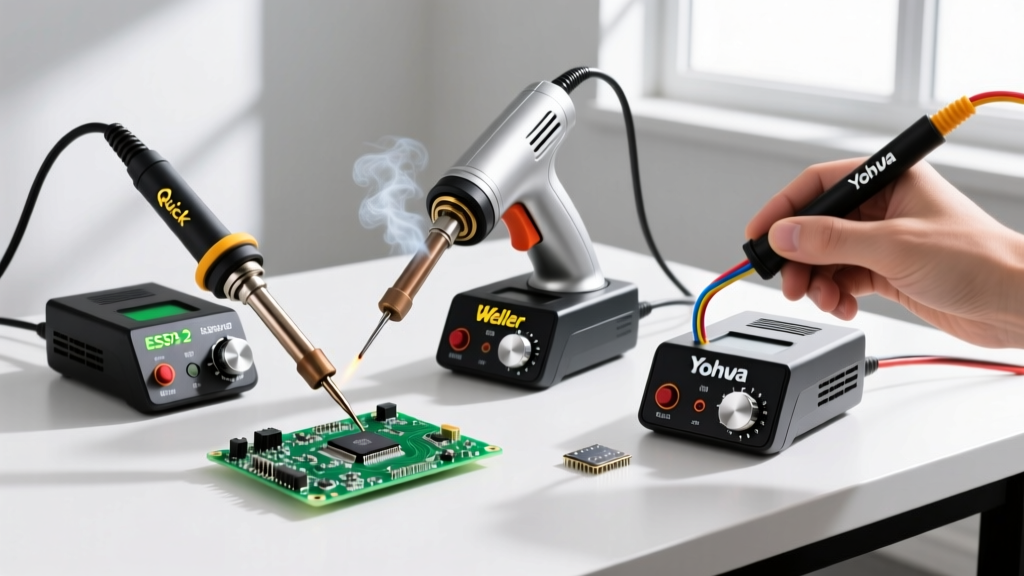
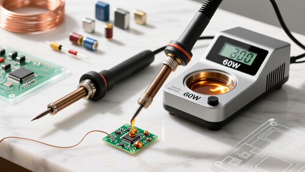
Modern active-tip systems, such as the JBC CD-2BQF (approx. $495) or the Pace ADS200 (approx. $320), integrate the heater and thermocouple directly into the consumable cartridge (e.g., JBC C245 or Pace TD-200 Blue Tip). This eliminates thermal lag, allowing the station to detect a temperature drop and inject compensating current in under 20 milliseconds. This is why a 70W JBC station will effortlessly solder a 14-gauge wire to a heavy ground plane, while a 100W generic iron with a passive tip will stall and create a cold joint.
Metallurgical Realities: The Intermetallic Compound (IMC)
To truly grasp the definition of soldering iron from an expert perspective, you must understand what happens at the molecular level. Soldering is not 'gluing' metal together; it is a localized alloying process. When molten solder (typically a Tin-Silver-Copper or Tin-Lead alloy) contacts a copper pad, a metallurgical reaction forms an Intermetallic Compound (IMC) layer, primarily Cu6Sn5 and Cu3Sn.
Expert Insight: The IMC layer is necessary for a joint's structural and electrical integrity, but it is inherently brittle. An ideal IMC thickness is between 1 to 3 micrometers. Excessive heat or prolonged dwell time causes the IMC layer to overgrow, leading to Kirkendall voids—microscopic gaps that make the joint highly susceptible to mechanical shock and thermal cycling fatigue.
Solder Alloy Thermal Profiles & Dwell Limits
The following matrix defines the precise thermal targets required to achieve optimal IMC formation without damaging the board's Tg (Glass Transition Temperature).
| Alloy Composition | Liquidus Temp | Optimal Tip Temp | Max Dwell Time | Primary Application |
|---|---|---|---|---|
| Sn63/Pb37 (Eutectic) | 183°C | 240°C - 270°C | 2.0 - 3.0 seconds | Prototyping, vintage repair, aerospace |
| SAC305 (Sn96.5/Ag3.0/Cu0.5) | 217°C - 220°C | 280°C - 320°C | 1.5 - 2.5 seconds | Modern RoHS commercial SMD/BGA |
| Sn96.5/Ag3.0/Cu0.5 (Low-Ag) | 217°C | 275°C - 310°C | 2.0 - 3.0 seconds | High-reliability automotive ECUs |
| Sn42/Bi57/Ag1 (Low Temp) | 138°C - 140°C | 180°C - 200°C | 3.0 - 4.0 seconds | Heat-sensitive flex-PCBs, step-soldering |
The Role of Flux in the Thermal Definition
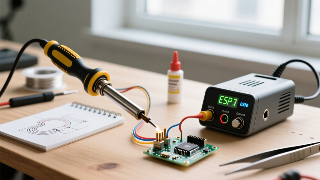
No expert definition of soldering iron systems is complete without addressing the thermal coupling agent: flux. Flux is not merely a cleaning agent; it is a vital component of the thermal transfer chain. At elevated temperatures, copper oxidizes instantly, creating a barrier with high thermal resistance. Flux (such as Amtech NC-559-V2-TF or MG Chemicals 8341) chemically reduces this oxide layer, allowing the molten solder to 'wet' the pad. More importantly, the liquid flux acts as a thermal bridge, transferring heat from the iron's tip to the joint via convection before the solder even melts. Attempting to solder a heavily oxidized via without fresh flux will cause the tip to dwell on the pad for 6+ seconds, inevitably delaminating the FR-4 substrate.
Hardware Translation: Matching the Definition to Modern Stations
Based on this advanced engineering definition, here is how top-tier stations in 2026 fulfill specific thermal requirements:
- JBC CD-2BQF (approx. $495): The undisputed king of thermal recovery. Its C245 cartridge system places the heater millimeters from the working edge. Ideal for mixed-technology boards where you transition from 0201 SMD resistors to heavy 10AWG XT60 battery connectors without changing the temperature dial.
- Pace ADS200 (approx. $320): Features the TD-200 handpiece with AccuDrive technology. It offers exceptional ergonomic balance and uses Blue Tips that rival JBC in thermal response, making it a favorite for high-volume production rework and micro-soldering under a microscope.
- Hakko FX-951 (approx. $280): A staple in manufacturing environments. While its T15-style composite tips have slightly more thermal mass than JBC's cartridges, its robust build and aggressive pricing make it the standard for continuous through-hole and heavy wire soldering.
- Pinecil V2 (approx. $26): Redefining the portable segment. Powered by a RISC-V processor and capable of 65W via USB-C PD3.0, it utilizes PID control and supports custom firmware (IronOS). While it lacks the raw thermal mass for massive ground planes, its precision makes it an incredible field-repair tool for drones and automotive diagnostics.
Failure Modes Driven by Misunderstanding Thermal Dynamics
When operators rely on the simplistic definition of soldering iron as just a 'heat source,' they inevitably encounter specific failure modes:
1. Copper Leaching and Tip Degradation
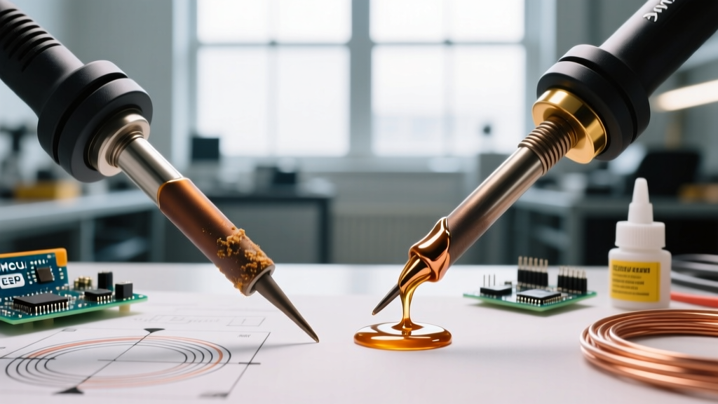
Soldering iron tips are not solid copper; they are copper cores plated with iron to resist erosion, and then tinned. If an operator leaves a SAC305 (lead-free) iron idling at 380°C, the aggressive tin in the solder will dissolve the iron plating—a process known as copper leaching. Once the iron layer is breached, the molten solder dissolves the copper core, creating a concave crater in the tip within hours. Expert Protocol: Always utilize auto-sleep features and dial back idle temperatures to 200°C when using lead-free alloys.
2. Pad Lifting and Measling
Applying downward physical pressure to force heat into a joint is a cardinal sin. Pressure does not improve thermal transfer; it degrades the tip's iron plating and risks cracking the vias. If a joint isn't heating, the issue is insufficient thermal mass (wrong tip geometry), inadequate flux, or an oxidized tip surface—not a lack of physical force. For large ground planes, switch from a fine conical tip (e.g., JBC C245-112) to a high-mass chisel or bevel tip (e.g., C245-945) to maximize surface area contact.
Expert Maintenance Protocols for Thermal Integrity
To maintain the closed-loop efficiency of your system, adhere to these strict maintenance parameters:
- Never use a wet sponge on lead-free tips. The rapid temperature drop (thermal shock) causes micro-fractures in the iron plating, accelerating oxidation and leaching. Use high-quality brass wire wool (like Hakko 599B) or a slightly damp, high-temp silicone tip cleaner.
- The 'Solder Blob' Storage Method. Before placing the iron in its holder, melt a generous blob of cheap, leaded 63/37 rosin-core solder onto the tip. This sacrificial layer acts as an oxygen barrier, preventing the working surface from oxidizing while idle. Wipe and re-tin with your working solder before the next joint.
- Calibrate Annually. Even high-end stations experience thermocouple drift. Use a specialized tip thermometer (e.g., Hakko FG-100) to verify that the digital readout matches the actual surface temperature of the tip within ±3°C.
Conclusion
Upgrading your mental model from the basic dictionary definition of soldering iron to an understanding of closed-loop thermal dynamics and metallurgy is the single most important step in transitioning from a hobbyist to a professional. By respecting the liquidus thresholds, managing thermal mass, and maintaining the integrity of your tip's plating, you ensure that every joint you create meets the rigorous IPC-A-610 Class 3 standards for high-reliability electronics. For further reading on industry workmanship standards, consult the IPC guidelines and practical tutorials like the Adafruit Guide to Excellent Soldering, or explore the technical metallurgy data provided by manufacturers like Hakko.