
The Metallurgy of Solder Iron Tips: Why Tinning Matters
To truly master the art of tinning a solder iron, you must first understand the complex metallurgy hiding beneath the surface of your iron's tip. Modern high-performance soldering tips—whether they are Hakko T18 series, Weller RT micro-tips, or Pace AccuDrive cartridges—are not solid pieces of metal. They are highly engineered, multi-layered composites designed for maximum thermal transfer and chemical resistance.
The core of the tip is typically high-purity copper, chosen for its exceptional thermal conductivity. However, molten solder aggressively dissolves copper. To prevent the core from being eaten away, manufacturers electroplate the copper with a layer of iron, usually between 100 and 150 microns thick. Above the iron plating is a micro-thin layer of chromium or nickel to prevent the solder from wetting the sides of the tip, and finally, the working face is pre-tinned with a layer of pure tin or tin-lead alloy.
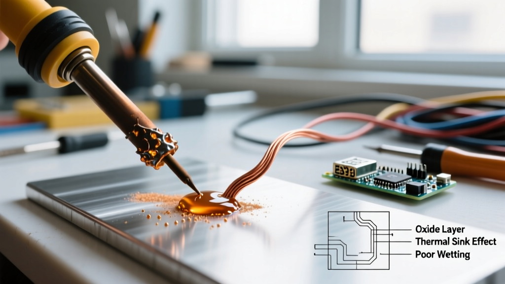
When you are tinning a solder iron, you are actively maintaining this outermost sacrificial layer. If this tin layer is compromised, the underlying iron plating is exposed to atmospheric oxygen at high temperatures. This rapidly forms iron oxide (rust) and tin oxide (SnO2). Tin oxide is a severe thermal insulator; a tip coated in black oxide will fail to transfer heat to your solder joints, resulting in cold joints, prolonged dwell times, and ultimately, thermal damage to your PCB pads.
The Oxidation Threshold: Temperature vs. Flux Degradation
Oxidation is a function of both time and temperature. The higher you set your soldering station, the faster the tinning layer degrades. Many hobbyists and even some technicians mistakenly believe that cranking a Hakko FX-888D or Weller WE1010NA up to 400°C+ will help them solder faster. In reality, this flash-burns the flux core inside the solder wire and accelerates tip oxidation exponentially.
According to Hakko America's Official Tip Care Guide, running a station at maximum temperature when not actively soldering can reduce tip life by up to 80%. The flux in your solder wire is designed to activate at specific temperatures; exceeding those thresholds turns the flux into a carbonized crust that actively repels molten solder.
Table: Tip Degradation Rates by Temperature
| Temperature (°C) | Oxidation Rate | Flux Behavior | Tip Lifespan Impact |
|---|---|---|---|
| 300 - 320°C | Slow | Optimal activation for 63/37 Sn/Pb | Maximum lifespan; ideal for general through-hole |
| 350 - 370°C | Moderate | Required for SAC305 Lead-Free alloys | Standard wear; requires frequent re-tinning |
| 400°C+ | Rapid / Severe | Flux carbonizes instantly; loses cleaning power | Destroys iron plating in weeks; high risk of pad lift |
Step-by-Step Protocol: Tinning a Solder Iron Correctly
Properly tinning a solder iron is not a one-time event; it is a continuous operational habit. Follow this exact protocol to ensure your tip remains wetted and protected throughout your work session.
- The Initial Heat-Up: Never walk away from a heating iron. As the tip approaches the melting point of your solder (183°C for eutectic Sn63/Pb37, or 217°C for SAC305), manually feed a generous amount of rosin-core solder onto the working face. The melting solder will flux the tip and protect it from the initial wave of oxidation.
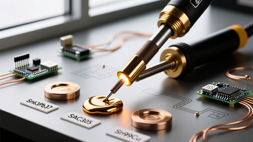
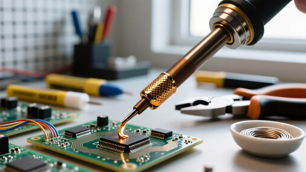
- The Sacrificial Storage Blob: Whenever you place the iron back into its holder, apply a large, thick dollop of solder to the tip. This 'blob' acts as a sacrificial anode. The outer layer of the blob will oxidize and turn dull, but the interior remains molten and protects the factory iron plating underneath.
- Pre-Joint Wipe and Re-Tin: Before making a solder joint, wipe the oxidized sacrificial blob off using your preferred cleaner (see below), and immediately apply fresh solder. Never wipe a tip and leave it bare to the air, even for five seconds. The sequence must be: Wipe → Apply Fresh Solder → Solder Joint.
Resurrection Protocol: Restoring a Severely Oxidized Tip
If you inherit a neglected iron or accidentally leave a station on overnight, you may be greeted by a tip encased in a hard, black, or blue crust. Never use sandpaper, a file, or a Dremel tool to clean the tip. Doing so will strip the 100-micron iron plating, instantly ruining the tip and exposing the copper core to rapid dissolution.
Instead, use a chemical-mechanical resurrection method. The NASA-STD-8739.3 Soldering Manual strictly prohibits abrasive cleaning of plated tips, recommending specialized tip tinning compounds instead.
- Set the station to a low temperature (around 250°C).
- Dip the blackened tip into a Tip Tinner compound (such as Hakko 599B or Weller WDC2). These compounds contain a mixture of mild abrasives, aggressive activated flux, and powdered solder.
- Swirl the tip in the compound for 3 to 5 seconds. The flux will strip the oxide, and the powdered solder will immediately wet the bare metal.
- Wipe the tip on brass wool to remove the carbonized flux residue.
- Apply fresh, high-quality rosin-core solder wire to seal the newly restored surface.
Brass Wool vs. Cellulose Sponges: The Thermal Shock Debate
The method you use to wipe your tip during the tinning process drastically affects its longevity. For decades, the damp cellulose sponge was the industry standard. However, modern metallurgical analysis reveals the hidden dangers of thermal shock.
When a 350°C tip touches a room-temperature damp sponge, it experiences an instantaneous temperature drop of over 300°C. This extreme thermal delta causes micro-fractures in the electroplated iron layer. Over time, these micro-cracks allow molten solder to seep through and attack the copper core, leading to 'copper leaching' and the formation of concave pits in the tip face.
Weller Soldering Tip Maintenance guidelines increasingly advocate for the use of brass wool shavings over sponges. Brass is softer than the iron plating, meaning it will not scratch the surface, and it does not contain water. Wiping on brass wool removes oxidized solder and carbonized flux without dropping the tip's core temperature, preserving the structural integrity of the iron plating and maintaining thermal stability for your next joint.
Advanced Tip Tinning Compounds and Flux Selection
The type of solder you use for the act of tinning matters just as much as the technique. While you may be required to use lead-free SAC305 (Tin/Silver/Copper) for your final PCB assemblies due to RoHS compliance, SAC305 has a higher melting point, poor wetting characteristics, and a higher tin content, which makes it more aggressive toward iron plating.
Expert Insight: For the specific act of tinning and maintaining your iron, keep a dedicated spool of 63/37 Sn/Pb eutectic solder with a thick Rosin Mildly Activated (RMA) flux core. The lower liquidus temperature (183°C) and superior wetting action of leaded solder create a vastly superior protective barrier on the tip, even if you subsequently wipe it and use lead-free solder for the actual component attachment.
If you are strictly in a lead-free environment and cannot introduce Sn/Pb into your workspace, you must use a lead-free tip tinner specifically formulated with high-reliability, no-clean or RMA fluxes designed for SAC alloys. Standard cheap, acid-core plumbing solder must never be used for electronics tinning, as the zinc chloride flux will permanently corrode the tip and contaminate your workstation.
Final Thoughts on Thermal Management
Ultimately, tinning a solder iron is an exercise in thermal and chemical management. By respecting the temperature limits of your station, avoiding thermal shock from wet sponges, and utilizing sacrificial solder blobs during idle periods, you can extend the life of a premium $50 soldering tip from a few weeks to several years. Treat the tinning layer as a vital, consumable component of your soldering ecosystem, and your joints will consistently reflect the high-quality thermal transfer that professional electronics demand.