
The 110V Soldering Iron: Navigating the North American Mains Reality
When electronics hobbyists and professional technicians search for a 'soldering iron 110v', they are tapping into a legacy colloquialism that masks a critical electrical reality. In North America, the standard residential and commercial alternating current (AC) mains voltage is nominally 120V, governed by the ANSI C84.1 standard. However, the term '110V' remains deeply entrenched in workshop vernacular, product search queries, and older equipment labeling. Understanding how your soldering station interacts with this specific AC voltage range—typically fluctuating between 108V and 126V in real-world conditions—is paramount for achieving reliable solder joints, especially when working with modern lead-free alloys and high-thermal-mass printed circuit boards (PCBs).
This feature deep dive explores the physics of heating elements at North American mains voltages, contrasts transformer-based and switch-mode power supply (SMPS) architectures, and provides actionable bench setup protocols to ensure your soldering station delivers consistent thermal recovery in 2026.
The Physics of Thermal Recovery and Voltage Fluctuations
To understand why your soldering iron's performance might waver on a crowded workshop circuit, we must look at the fundamental relationship between voltage, resistance, and power. According to Joule's first law, power (P) is equal to the square of the voltage (V) divided by the resistance (R) of the heating element. As detailed in the All About Circuits power textbook, this squared relationship means that even minor voltage drops have a magnified impact on thermal output.
The Brownout Effect: If a 70W soldering station is engineered for exactly 120V, its heating element possesses a resistance of approximately 205 ohms. If your bench is located at the end of a long extension cord or a heavily loaded circuit, and the wall voltage sags to 108V (a common 10% brownout scenario), your available power drops to roughly 56.8W. That is a 19% loss in thermal recovery capability, which can easily result in cold solder joints when dragging through large ground planes.
This voltage sensitivity is precisely why modern soldering stations utilize closed-loop temperature control. The microcontroller monitors the thermocouple embedded in or near the tip and pulses power to the element to maintain the setpoint. However, if the available wattage drops due to low mains voltage, the system simply cannot replenish heat fast enough when a massive copper pour acts as a heatsink.
Heating Element Technologies: Nichrome vs. Ceramic
The type of heating element inside your 110V/120V iron dictates how efficiently it converts electrical energy into localized heat at the tip.
- Nichrome Wire Elements: Found in older or budget-friendly irons, nichrome wire wraps around the tip barrel. Heat must transfer through an air gap and ceramic insulator. While robust against voltage spikes, they suffer from slower thermal recovery and higher tip-to-heater thermal resistance.
- Ceramic (PTC) Elements: Standard in premium 2026 stations (like the Hakko T18 or Weller RT series). The heating trace and thermocouple are printed directly onto a ceramic substrate that inserts into a hollow tip. This provides near-instant thermal transfer and highly accurate closed-loop feedback, maximizing the utility of whatever wattage the 120V mains can provide.
Power Supply Architectures: Transformer vs. SMPS
The base station of your soldering iron must step down the 110V/120V AC mains to a safer, manageable DC or low-voltage AC level for the handpiece. The method used to achieve this drastically affects the tool's weight, efficiency, and susceptibility to dirty power.
Iron-Core Transformers
Legacy workhorses like the Weller WES51 utilize heavy, copper-wound iron-core transformers. These are virtually indestructible, completely immune to high-frequency switching noise, and can handle massive inrush currents without voltage sag. The tradeoff is immense physical weight and lower efficiency, generating noticeable heat inside the chassis even when the iron is holstered.
Switch-Mode Power Supplies (SMPS)
Modern stations, including the ubiquitous Hakko FX-888D and advanced smart irons like the Pinecil V2, rely on SMPS architecture. These circuits switch the 120V AC mains at high frequencies, allowing for much smaller, lighter transformers. SMPS units are highly efficient and maintain stable DC output even if the input AC voltage fluctuates between 100V and 240V. However, cheap, unbranded SMPS adapters can inject electromagnetic interference (EMI) back into your bench's ground plane, potentially disrupting sensitive oscilloscope measurements or microcontroller programming.
2026 Market Matrix: Top 110V/120V Soldering Stations
The following table benchmarks the most prominent soldering systems operating on North American mains voltage available in 2026, highlighting their power delivery and element types.
| Model | Mains Input | Max Wattage | Element / Tip Ecosystem | Power Supply Type | Approx. Price (USD) |
|---|---|---|---|---|---|
| Hakko FX-888D | 120V AC | 70W | Ceramic / T18 Series | Internal SMPS | $115 - $130 |
| Weller WE1010 | 120V AC | 70W | Ceramic / ET Series | Internal SMPS | $120 - $140 |
| Pine64 Pinecil V2 | 110-240V AC (via adapter) | 65W (at 24V DC) | Ceramic / TS100/BC2 Compatible | External USB-C PD / DC Brick | $26 (Iron) + $15 (PSU) |
| Weller WES51 | 120V AC | 50W | Nichrome / ETA Series | Iron-Core Transformer | $130 - $150 (Refurb/Used) |
| JBC CD-2BQE | 110-120V AC | 130W (Peak) | Integrated Cartridge / C245 | Advanced Digital SMPS | $450 - $490 |
Cross-Voltage Catastrophes: The 220V vs. 110V Trap
One of the most frequent and destructive edge cases in electronics labs involves mixing up regional power cords or importing soldering stations without verifying the internal voltage dip switches.
Plugging a 220V/240V Iron into a 110V/120V Socket
If you connect a European 230V soldering iron to a North American 120V outlet, the iron will not explode, but it will severely underperform. Because power is proportional to the square of the voltage, running a 230V element at 120V yields roughly 27% of its rated wattage. A 50W iron will output a mere 13.5W. The station will struggle to reach 350°C, making it impossible to properly reflow SAC305 lead-free solder, which requires strict adherence to thermal profiles to avoid the defects outlined in the IPC J-STD-001 standard.
Plugging a 110V/120V Iron into a 220V/240V Socket
This is a catastrophic failure mode. The element will attempt to draw four times its rated power. Within milliseconds, the nichrome or ceramic trace will vaporize. In stations with triac-based AC switching, the overvoltage will likely cause the triac to short-circuit and detonate, sending shrapnel inside the chassis and instantly tripping the workshop's GFCI or MCB breaker. Always verify the voltage selector switch on the rear panel of analog stations before applying power.
Actionable Bench Setup for Optimal 110V/120V Delivery
To guarantee your soldering station receives clean, stable voltage, implement the following infrastructure protocols on your workbench:
- Audit Your Extension Cords: Never power a 70W+ soldering station and a heat gun simultaneously on a 16 AWG extension cord. The resistance of thin copper over a 25-foot run will induce a voltage drop, starving your iron's SMPS. Use heavy-duty 12 AWG or 14 AWG cords for bench power distribution.
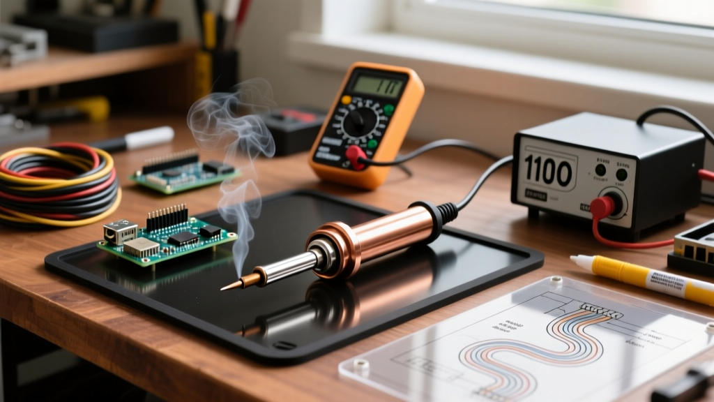
- Verify with a True RMS Multimeter: Do not rely on cheap digital plug-in voltage monitors. Use a calibrated True RMS multimeter to measure the AC voltage at your bench receptacle under load. If you consistently read below 114V, consult an electrician to check for loose neutral bonds or overloaded branch circuits.
- Isolate from Inductive Loads: Plug your soldering station into a circuit separate from heavy inductive loads like bench grinders, drills, or large dust collectors. The back-EMF generated when these motors switch off can induce voltage spikes that degrade the capacitors inside your iron's SMPS over time.
- Leverage a Double-Conversion UPS: For high-precision micro-soldering or BGA rework stations (like the JBC or Pace ADS200), consider routing the bench receptacle through an online, double-conversion Uninterruptible Power Supply (UPS). This regenerates a pure, continuous 120V sine wave, completely isolating your thermal tools from grid brownouts and harmonic distortion.
Conclusion: Respecting the Mains
While 'soldering iron 110v' remains the dominant search paradigm, the modern electronics technician must treat the North American 120V mains as a dynamic variable rather than a static guarantee. By understanding the squared relationship between voltage and thermal recovery, selecting the appropriate SMPS or transformer architecture for your specific EMI tolerance, and properly configuring your bench wiring, you ensure that your soldering station operates at peak efficiency. Whether you are dragging a wide chisel tip across a multi-layer motherboard or executing delicate 0201 component rework with a micro-pencil, stable voltage delivery is the invisible foundation of every reliable solder joint. For further foundational techniques on managing thermal mass and joint geometry, the SparkFun through-hole soldering guide remains an excellent companion resource to pair with your optimized bench power setup.