
What Is Soldering Paste? The Core Definition
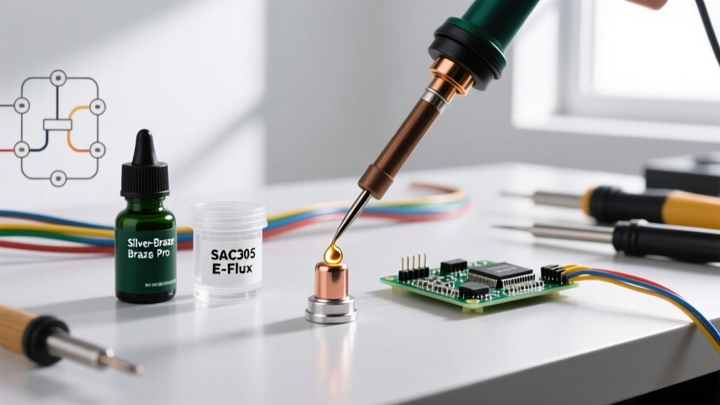
If you are transitioning from through-hole soldering to Surface Mount Technology (SMT), or simply looking to refine your PCB prototyping workflow, you will inevitably ask: what is soldering paste? Unlike traditional solder wire, solder paste is a precise, thixotropic mixture consisting of microscopic spherical metal alloy powder suspended in a sticky, gel-like flux medium.
At room temperature, the flux vehicle acts as a temporary adhesive, holding surface-mount components firmly in place on the PCB pads. When exposed to heat in a reflow oven or on a hotplate, the flux activates to remove oxidation, and the metal powder melts (reflows) to form a permanent, conductive metallurgical bond. According to the IPC standards governing electronics assembly, solder paste is the lifeblood of modern SMT manufacturing, dictating both the electrical reliability and the mechanical strength of the final joint.
The Anatomy of Solder Paste: Alloy and Flux
To select the right paste, you must understand its two primary components. The ratio is typically 85% to 90% metal powder by weight, with the remaining 10% to 15% being the flux vehicle.
1. The Metal Alloy Powder
The alloy determines the melting point, mechanical strength, and electrical conductivity of the joint. The two most common categories are:
- Leaded (Sn63/Pb37 or Sn60/Pb40): Melts at a low 183°C (361°F). Sn63/Pb37 is a eutectic alloy, meaning it transitions instantly from solid to liquid without a plastic (semi-solid) phase, resulting in shiny, reliable joints with minimal cold-joint risk.
- Lead-Free (SAC305 - Sn96.5/Ag3.0/Cu0.5): The industry standard for RoHS-compliant commercial manufacturing. It melts at a higher 217°C (423°F) and requires tighter thermal profiling to avoid component damage.
2. The Flux Vehicle
The flux is not just a cleaning agent; it provides the paste's viscosity and tackiness. For a deep dive into advanced flux formulations and wetting agents, manufacturers like Indium Corporation publish extensive technical data sheets detailing how specific rosin resins prevent solder balling and bridging.
IPC Powder Size Classifications: Type 3 vs. Type 4 vs. Type 5
One of the most critical factors in answering 'what is soldering paste' in a practical sense is understanding powder mesh size. The IPC J-STD-005 standard categorizes solder powder by particle diameter. Choosing the wrong type will lead to stencil clogging or insufficient solder volume.
| Paste Type | Particle Size (Microns) | Best Use Case | Typical Component Pitch |
|---|---|---|---|
| Type 3 | 25 - 45 µm | Standard SMT, DIY prototyping, hand stenciling | > 0.5mm (e.g., SOIC, 0805, 1206) |
| Type 4 | 20 - 38 µm | Fine-pitch SMT, automated stencil printing | 0.4mm - 0.5mm (e.g., QFP, 0402, 0603) |
| Type 5 | 15 - 25 µm | Ultra-fine pitch, micro-BGA, advanced SMT | < 0.3mm (e.g., 0201, CSP, micro-BGA) |
| Type 6 | 5 - 15 µm | Semiconductor packaging, flip-chip | < 0.15mm |
Expert Tip: For most DIY electronics hobbyists and small-batch prototyping using laser-cut stainless steel stencils, Type 3 or Type 4 offers the best balance of printability and cost. Type 5 and 6 are significantly more expensive and prone to oxidation if not handled in nitrogen-rich environments.
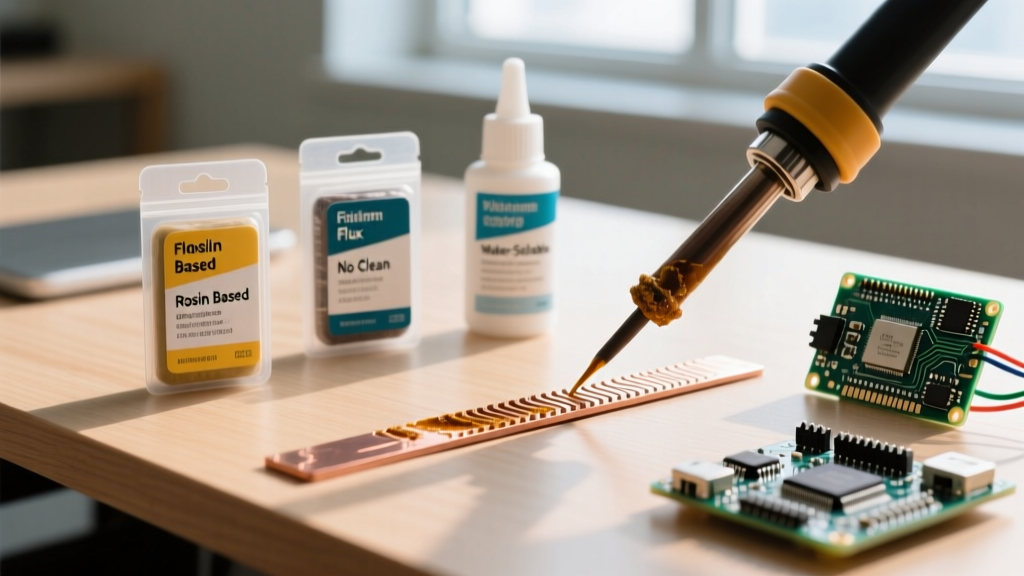
Flux Chemistries: No-Clean vs. Water-Soluble
The flux chemistry dictates your post-reflow cleaning requirements. The IPC J-STD-004 standard classifies fluxes based on activity and residue.
No-Clean Flux (e.g., ROL0, ROL1)
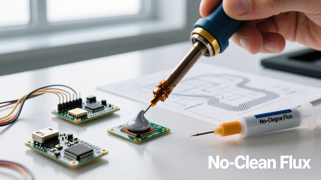
No-clean pastes leave behind a clear, hard, and electrically inert residue after reflow. This residue is designed to be left on the PCB, saving time and eliminating the need for harsh chemical solvents. They are the undisputed standard for modern consumer electronics and DIY projects. However, if you are building high-impedance analog circuits or RF boards, you may still want to clean the residue to prevent parasitic capacitance.
Water-Soluble Flux (e.g., ORH0, ORH1)
Water-soluble (OA - Organic Acid) pastes are highly active, providing excellent wetting on oxidized or difficult-to-solder pads. The trade-off is that the residue is highly corrosive and conductive. It must be aggressively cleaned using heated deionized (DI) water and ultrasonic agitation immediately after reflow. If you skip cleaning, the board will suffer from dendritic growth and eventual short-circuit failure.
Packaging Formats and Real-World Selection
When sourcing paste from suppliers like DigiKey or Mouser, you will encounter different packaging formats. Your choice should align with your application method:
- 10cc - 35g Syringes: Ideal for manual dispensing via pneumatic syringe barrels or direct hand application for quick rework. Cost benchmark: A 35g syringe of Chip Quik SMD291AX (Sn63/Pb37, Type 3, No-Clean) typically retails for $28 - $32.
- 300g - 500g Jars: Required for stencil printing. You use a metal or plastic spatula to roll the paste across the stencil aperture. Cost benchmark: A 500g jar of Kester EP256 (SAC305, Type 4) costs between $85 and $110.
- Cartridges: Designed for automated inline SMT pick-and-place and stencil printing machines.
Critical Handling: The 2-Hour Warmup Rule
Solder paste degrades rapidly at room temperature. The flux solvents evaporate, and the paste turns into a thick, unusable putty. Therefore, paste must be stored in a refrigerator between 0°C and 10°C (32°F - 50°F).
The Condensation Trap: When you remove a jar or syringe from the fridge, do not open it immediately. You must let it sit at room temperature for 2 to 4 hours. Opening cold paste exposes it to ambient humidity, causing instantaneous condensation inside the jar. When this water-laden paste hits a 240°C reflow oven, the water flashes into steam, causing violent solder balling and micro-splattering across your PCB.
Troubleshooting Common Paste Failures
Even with the right alloy and stencil, incorrect paste handling or reflow profiling leads to distinct failure modes. Here is how to diagnose them:
| Failure Mode | Visual Symptom | Root Cause & Solution |
|---|---|---|
| Tombstoning | One end of a 2-terminal component (like a capacitor) lifts vertically off the pad. | Uneven heating or excessive paste volume on one pad causing unequal wetting forces. Reduce stencil aperture size for the affected pad. |
| Solder Balling | Tiny, disconnected spheres of solder scattered around the main joint. | Moisture in the paste (failed warmup rule) or a reflow ramp-up rate that is too fast, causing flux solvents to boil explosively. |
| Bridging (Shorts) | Solder connects two adjacent fine-pitch pins. | Stencil misalignment, excessive paste deposition, or using Type 3 paste on a 0.4mm pitch IC where Type 4 is required. |
| Head-in-Pillow | BGA sphere rests on top of the paste deposit without metallurgical merging. | Oxidation on the BGA spheres or insufficient peak temperature/Time Above Liquidus (TAL) during reflow. |
Reflow Profiling: Time Above Liquidus (TAL)
Understanding what soldering paste is also means understanding how it reacts to heat. For lead-free SAC305 pastes, your reflow profile must achieve a peak temperature of 235°C to 245°C. More importantly, the Time Above Liquidus (TAL)—the duration the paste spends above its 217°C melting point—must be strictly maintained between 45 and 90 seconds. A TAL that is too short results in grainy, dull, and brittle cold joints; a TAL exceeding 120 seconds accelerates copper pad dissolution and risks delaminating the PCB substrate.
Final Thoughts on Paste Selection
Selecting the right solder paste is a balancing act between your component pitch, your thermal profile, and your post-assembly cleaning capabilities. For general DIY and prototyping, a Sn63/Pb37 Type 3 No-Clean paste in a syringe offers the most forgiving thermal window and excellent wetting. For commercial, RoHS-compliant production, a SAC305 Type 4 paste applied via precision laser-cut stencils remains the undisputed industry standard.
For further reading on advanced metallurgical joint reliability and flux classifications, consult the technical resources provided by Kester Assembly Materials and the IPC assembly guidelines.