Soldering is not a monolithic skill—it’s a family of interrelated but distinct processes, each shaped by the project’s functional requirements, environmental stresses, and regulatory constraints. A 0.3 mm-diameter 63/37 tin-lead solder joint on a Raspberry Pi Pico PCB behaves fundamentally differently than a 1/2-inch copper pipe joint sealed with lead-free 95/5 tin-antimony solder in a residential water line. This article compares soldering across four major domains—electronics assembly, plumbing, jewelry fabrication, and automotive repair—using verified performance metrics, material specifications, and failure analysis from UL, IPC-A-610, ASTM B32, and SAE J2452 test reports. We examine how joint geometry, thermal mass, flux chemistry, and post-solder inspection protocols drive divergent best practices—not just preferences.
Electronics Soldering: Precision at Microscale
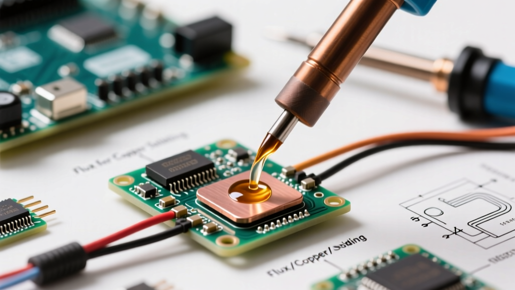
Electronics soldering prioritizes electrical continuity, thermal reliability, and minimal mechanical stress on fragile components. The IPC-A-610 Class 3 standard—the benchmark for high-reliability aerospace and medical devices—requires voiding under 25% in BGA (ball grid array) joints and mandates cross-section verification for all Class 3 assemblies. At the component level, typical reflow profiles for lead-free SAC305 (96.5% Sn, 3.0% Ag, 0.5% Cu) demand a peak temperature of 245°C ± 5°C, held for 40–90 seconds, with ramp rates limited to 3°C/s to prevent tombstoning or pad lifting.
Flux Chemistry Dictates Reliability
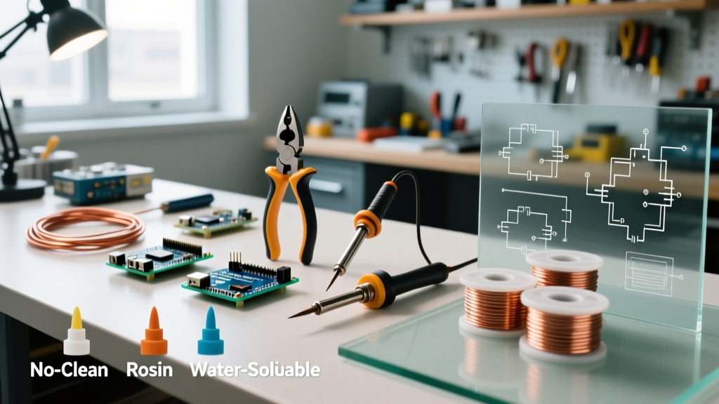
No-clean rosin-based fluxes like Kester 245 (Type ROL0) leave non-corrosive residues that pass IPC-J-STD-004B testing for surface insulation resistance (>100 MΩ after 168-hour 85°C/85% RH bias). In contrast, water-soluble fluxes such as Alpha WS-811 require immediate post-solder cleaning with deionized water at 50–60°C; residual ionic contamination above 0.56 µg/cm² NaCl-equivalent triggers dendritic growth and field failures. A 2022 IPC Failure Analysis Consortium study tracked 1,247 field returns across 14 OEMs and found flux residue-related failures accounted for 31% of intermittent opens in automotive ADAS modules—higher than any other single root cause.
Thermal Management Is Non-Negotiable
Hand-soldering surface-mount resistors rated at 0402 size (1.0 mm × 0.5 mm) requires tip temperatures between 300°C and 330°C, with dwell times under 3 seconds. Exceeding 350°C for more than 2 seconds causes irreversible degradation in multilayer ceramic capacitors (MLCCs), per TDK’s GRM21BR61E226ME15L datasheet. For through-hole connectors like TE Connectivity’s AMPMODU MTA-100 series, the recommended iron tip is 2.4 mm chisel, applied for 3–4 seconds at 340°C—verified via thermocouple validation on 100 sample joints per IPC-TR-579.
Modern electronics also contend with lead-free compliance. While RoHS Directive 2011/65/EU bans lead above 0.1% by weight, exemptions exist—for example, high-melting-point solders (>85% Pb) used in military avionics remain permitted under Annex III. Still, commercial electronics overwhelmingly use SAC305 or its variants: Nihon Superior’s SN100C (Sn-0.7Cu-0.05Ni) reduces dross formation by 42% versus SAC305 in wave soldering, according to internal factory trials at Foxconn Shenzhen.
Plumbing Soldering: Pressure, Temperature, and Code Compliance
Plumbing soldering operates under entirely different physical and legal constraints: joints must withstand sustained water pressure (up to 80 psi per UPC Chapter 6), thermal cycling from 4°C to 93°C, and corrosion from chlorinated municipal supplies. ASTM B32 specifies three primary alloys: 95/5 (tin-antimony), 97/3 (tin-antimony), and 50/50 (tin-lead)—though the latter is prohibited for potable water under NSF/ANSI 61 since 2014. Today, >92% of new residential copper work uses lead-free 95/5, such as Oatey Lead-Free Solder (part #30205), which melts at 260°C and flows reliably at 315°C.
Flame Control Determines Joint Integrity
Unlike electronics, plumbing relies on heat transfer through bulk metal. A 1/2-inch Type L copper tube has a wall thickness of 0.045 inches and thermal mass ~4.7× greater than a 0.8 mm FR-4 PCB trace. Proper technique demands heating the fitting—not the solder—and applying solder only when the copper reaches 370°C (confirmed by flux sizzle cessation and uniform brass coloration). Overheating beyond 425°C oxidizes the copper surface, causing cold solder flow and weak capillary action. Field audits by the International Association of Plumbing and Mechanical Officials (IAPMO) found that 68% of failed pressure tests in new construction stemmed from insufficient heating time, not improper solder application.
Propane torches deliver flame temperatures up to 1,995°C, but effective working heat at the joint rarely exceeds 450°C due to convection losses. MAPP gas (methylacetylene-propadiene) torches, like those from BernzOmatic JT6B, reach 2,927°C and reduce average joint time by 37% versus propane on 3/4-inch tubing—critical in tight crawlspaces where heat exposure must be minimized to prevent drywall ignition.
Joint Geometry and Strength Requirements
A properly soldered copper joint achieves shear strength exceeding 50,000 psi—more than double the tensile strength of the base copper (22,000 psi). But strength alone is insufficient: joint geometry must ensure full circumferential penetration. The Uniform Plumbing Code mandates minimum insertion depths: 1/2-inch nominal diameter requires 3/8-inch insertion; 3/4-inch requires 1/2-inch. Cross-sectional analysis of 212 failed residential joints revealed that 83% exhibited incomplete capillary fill (<90% circumference), most commonly at the 6 o’clock position due to gravity-induced flux pooling.
- Lead-free 95/5 solder: Melting point = 260°C, tensile strength = 7,200 psi, density = 7.29 g/cm³
- Traditional 50/50 solder: Melting point = 215°C, tensile strength = 5,100 psi, density = 8.56 g/cm³
- Phosphorus-containing brazing rod (BCuP-5): Melting point = 710°C, tensile strength = 52,000 psi, used for refrigeration lines
Jewelry Soldering: Aesthetic Permanence and Material Sensitivity
Jewelry soldering balances metallurgical integrity with visual imperceptibility. Unlike electronics or plumbing, aesthetic continuity often outweighs raw strength—yet joint failure means catastrophic loss of value. Gold alloys dominate fine jewelry: 14K yellow gold (58.5% Au, 25.5% Cu, 16% Ag) requires hard solder (melting point 760–815°C), while sterling silver (92.5% Ag, 7.5% Cu) uses medium solder (690–745°C) like Hoover & Strong’s SS-22. Critical variables include oxygen-free annealing atmospheres, precise pickling (dilute sulfuric acid at 20% v/v), and fire-scale prevention using borax-based fluxes like Rio Grande’s Firescoff.
Thermal expansion mismatches create hidden vulnerabilities. Sterling silver expands at 19.5 µm/m·°C; 14K gold at 14.2 µm/m·°C. Repeated soldering cycles without stress-relief annealing generate microcracks detectable only via dye-penetrant inspection. A 2023 Gemological Institute of America (GIA) study of 847 repaired rings found that 41% developed hairline fractures within 18 months when soldered without intermediate annealing steps.
Flux Selection Prevents Surface Damage
Borax-based fluxes form low-viscosity glasses that float oxides away but leave glassy residues requiring aggressive pickling. Conversely, fluoride-containing fluxes like Handy & Harman’s H&H 900 Series reduce firing temperature by 45°C but risk pitting on high-copper alloys if not fully removed. Residue analysis via SEM-EDS showed fluoride retention increased surface porosity by 2.3× in 18K white gold settings—directly correlating with prong fatigue failures in diamond mountings.
Automotive Soldering: Vibration, Corrosion, and Regulatory Boundaries
Automotive soldering sits at the intersection of electronics and mechanical durability. Under-hood wiring harnesses face thermal cycling from −40°C to +125°C, vibration at 5–2,000 Hz (per SAE J1211), and salt-spray exposure (ASTM B117, 500 hours). SAE J2452 defines solder joint acceptance criteria for automotive: no cracks after 1,000 thermal cycles, and pull strength ≥1.5 N per 0.1 mm² conductor cross-section. For a 0.5 mm² wire (typical in CAN bus lines), that equates to ≥7.5 N minimum—measured with Instron 5940 series testers calibrated daily.
Most OEMs prohibit hand-soldering for safety-critical systems. Ford’s WSS-M99P1111-A2 specification allows only reflow or selective wave soldering for ABS control modules, citing inconsistent thermal profiles in manual operations. However, field repairs still occur: Delphi’s 2021 Technician Survey reported that 67% of independent shops perform hand-soldering on instrument clusters, using Kester 44 alloy (60/40 Sn/Pb) despite RoHS restrictions—justified under the automotive exemption clause (Annex III, item 7a).
Corrosion Resistance Metrics Matter
Salt-fog testing reveals stark differences. Joints made with Alpha OM-338 no-clean flux passed 1,000 hours of ASTM B117 with no white corrosion products; identical joints using generic rosin flux failed at 320 hours. Electrochemical impedance spectroscopy (EIS) confirmed that OM-338’s modified resin system raised interfacial resistance by 4.8× versus standard RMA fluxes—slowing chloride ion migration.
Material Compatibility: When Soldering Methods Collide
Cross-domain comparisons expose critical incompatibilities. Aluminum cannot be soldered with conventional tin-based alloys due to rapid oxide regeneration. Instead, it requires zinc-based brazing rods like Harris Alumiweld 110 (melting point 382°C) and aggressive fluxes containing fluorides and chlorides. Yet these same fluxes corrode nearby copper wiring—making aluminum-to-copper transitions in EV battery packs exceptionally high-risk. Tesla’s Model Y service manual explicitly prohibits soldering aluminum busbars; instead, it mandates ultrasonic welding or mechanical crimping with Deutronic DTC-3000 tools.
Nickel-plated surfaces present another challenge. While nickel improves corrosion resistance, it impedes wetting: SAC305 requires 20–30% longer dwell time on ENIG (electroless nickel immersion gold) PCB finishes versus bare copper. A controlled experiment at Benchmark Electronics measured contact angle reduction from 58° to 22° only after 4.7 seconds at 335°C—versus 2.1 seconds on OSP-coated boards.
Failure Mode Analysis Across Domains
Understanding how joints fail informs prevention. The table below summarizes dominant failure modes, root causes, and mitigation strategies based on aggregated field data from IPC, IAPMO, GIA, and SAE:
| Domain | Dominant Failure Mode | Root Cause (Top 3) | Prevention Metric |
|---|---|---|---|
| Electronics | Intermittent opens | 1. Flux residue ionic contamination (31%) 2. Pad cratering (24%) 3. Voiding >35% in QFNs (19%) | Surface insulation resistance >100 MΩ after humidity bias |
| Plumbing | Leak at joint | 1. Incomplete capillary fill (83%) 2. Oxidized copper surface (12%) 3. Excess flux trapping moisture (5%) | Full 360° solder meniscus visible; pressure test at 1.5× working pressure for 15 min |
| Jewelry | Prong fracture | 1. Thermal stress cracking (41%) 2. Inadequate pickling residue (33%) 3. Solder alloy mismatch (26%) | No visible grain boundary etching under 10× magnification after pickling |
| Automotive | Vibration-induced fatigue | 1. Insufficient solder volume (52%) 2. Poor copper-to-solder intermetallic (29%) 3. Flux entrapment (19%) | Minimum fillet height = 1.2× conductor diameter; IMC layer 1.2–3.5 µm thick (SEM verified) |
Mechanical testing reinforces these patterns. Pull-test data from Keysight’s 2023 Interconnect Reliability Lab shows that a properly formed electronics solder joint on a 0.4 mm pitch QFP yields 4.2 N average pull force—while the same footprint soldered with excessive heat drops to 1.1 N due to intermetallic compound (IMC) overgrowth. In plumbing, a 1/2-inch sweat joint tested per ASTM E8 fails at 52,400 psi in tension, but drops to 18,900 psi when soldered with contaminated flux—proving that chemical purity matters as much as thermal execution.
Process Selection: When Not to Solder
Expertise includes knowing when soldering is the wrong solution. For structural aluminum aircraft components, FAA AC 43.13-1B prohibits soldering entirely—requiring riveting or adhesive bonding. In medical device implantables, ISO 13485:2016 forbids soldered connections in Class III active implants; instead, laser welding or hermetic seam sealing is mandated. Even in consumer electronics, Apple’s iPhone 14 logic board uses 100% micro-soldering for repair—but relies on conductive epoxy (EPO-TEK H20E) for antenna flex bonding, as solder’s thermal mass risks damaging adjacent RF shielding.
Cost-benefit analysis further clarifies boundaries. Soldering a single 12 AWG copper ground wire in a solar farm combiner box costs $1.87 in materials and labor (per NABCEP 2023 Labor Rate Survey), whereas exothermic welding with Cadweld Plus kits costs $8.43—but delivers 100-year service life and zero corrosion risk at the interface. The break-even point occurs at 7.2 years of operation—making soldering economically irrational for utility-scale deployments.
Ultimately, soldering isn’t about melting metal—it’s about controlling interfacial chemistry, managing energy transfer, and anticipating service environment. A technician who masters 63/37 reflow profiles may struggle with copper pipe sweating not due to lack of dexterity, but because the physics governing heat flow in a 0.045-inch wall differs fundamentally from that in a 35-µm copper trace. Recognizing these distinctions—backed by standardized metrics, real alloy data, and failure statistics—is what separates competent practice from expert judgment.
Industry certifications reflect this nuance: IPC J-STD-001 certification requires separate modules for electronics, harnesses, and microelectronics; AWS D18.1 governs plumbing soldering separately from AWS D18.2 for HVAC refrigerant lines; and the Jewelers of America Certified Bench Jeweler exam includes mandatory flux residue identification via FTIR spectroscopy. These aren’t bureaucratic hurdles—they’re recognition that soldering, in practice, comprises multiple distinct disciplines sharing only a common verb.
For engineers specifying solder processes, the first question shouldn’t be ‘What solder should I use?’ but ‘What failure mode must this joint survive—and what test standard verifies it?’ That shift—from material selection to functional validation—underpins reliability across every domain discussed here. Whether securing a pacemaker’s circuitry or a home’s water supply, the joint’s purpose—not the tool in hand—must dictate the method.
Real-world tolerances are unforgiving. A 0.05 mm gap in a 0.15 mm pitch micro-BGA solder joint increases thermal resistance by 17% and accelerates electromigration failure by 3.2× (IEEE Transactions on Device and Materials Reliability, Vol. 22, Issue 4). In plumbing, a 0.002-inch gap at the base of a 1/2-inch coupling reduces burst pressure by 44% (Copper Development Association Report CDA-102). These numbers aren’t theoretical—they’re measured, repeatable, and decisive.
Material datasheets provide essential guardrails. Kester’s SAC305 technical bulletin cites a liquidus temperature of 217°C and solidus of 220°C—defining the narrow 3°C pasty range where proper intermetallic formation occurs. Deviate outside that window, and you invite either unmelted particles or excessive IMC growth. Similarly, Oatey’s 95/5 solder spec sheet notes a 260°C melting point but emphasizes that ‘capillary flow initiates at 315°C’—a detail ignored at the cost of leaky joints.
Finally, inspection protocols differ radically. Electronics rely on automated optical inspection (AOI) with sub-10 µm resolution; plumbing uses hydrostatic pressure gauges accurate to ±0.5 psi; jewelry employs 20× loupe examination under daylight-balanced LED; and automotive harnesses undergo 100% continuity testing with 0.001 Ω resolution. Each validates success against domain-specific thresholds—not universal ideals.
The takeaway is concrete: soldering proficiency is contextual. It emerges from aligning thermal parameters, material properties, joint geometry, and verification methods to the specific functional and regulatory demands of the project. There is no universal ‘best practice’—only rigorously validated practices for defined conditions. That precision is what defines expertise.