
Introduction to Solder Paste Material Science
When hobbyists and engineers alike think about assembly, they often view solder paste merely as a metallic glue. However, from a materials science perspective, soldering paste for electronics is a highly engineered, multiphase rheological fluid. It is a temporary suspension system designed to deliver precise metallurgical precursors and chemical cleaning agents to a joint, only to undergo radical phase transformations during the reflow process. Understanding the underlying chemistry and metallurgy of this consumable is critical for achieving reliable intermetallic bonds, especially as component pitches shrink to sub-millimeter dimensions in modern PCB designs.
In this comprehensive guide, we will deconstruct the material science of solder paste, examining the alloy powder characteristics, the complex organic flux vehicle, and the thermodynamic phase changes that dictate joint reliability. Whether you are hand-stenciling a prototype or optimizing a reflow profile for a high-density interconnect (HDI) board, mastering these fundamentals will elevate your assembly yields.
The Metallurgical Core: Solder Powder and Alloy Science
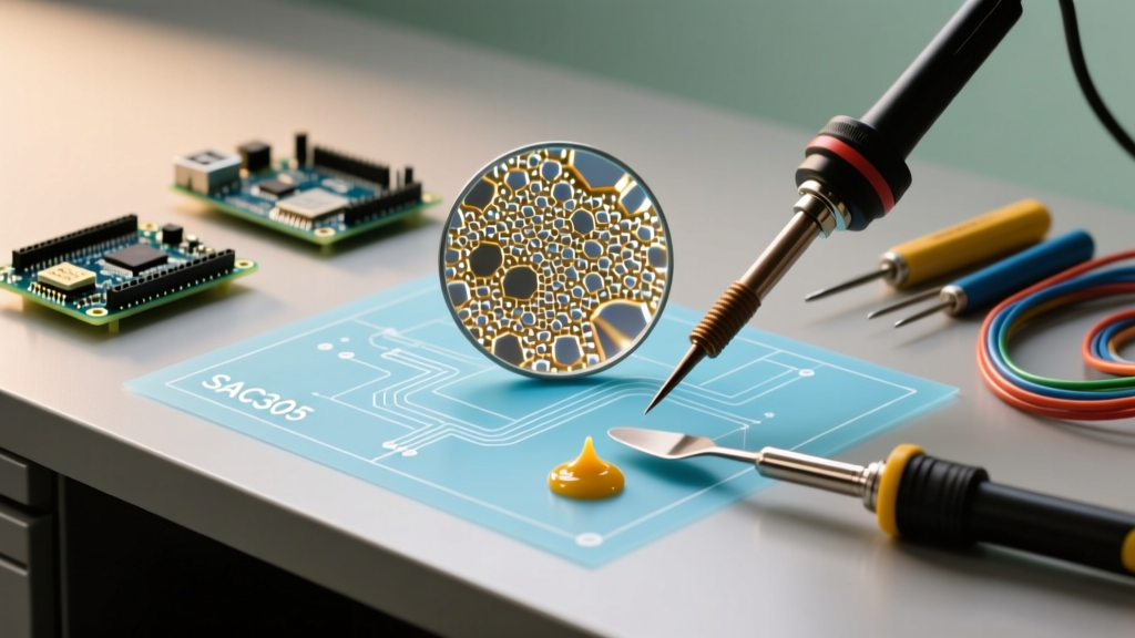
The metallic component of solder paste typically constitutes 85% to 92% of the total weight (and about 50% of the volume). The most ubiquitous lead-free alloy in the industry remains SAC305 (96.5% Tin, 3.0% Silver, 0.5% Copper). From a metallurgical standpoint, the addition of silver and copper to the tin matrix lowers the melting point from pure tin's 232°C to a near-eutectic 217°C, while simultaneously enhancing the shear strength and thermal fatigue resistance of the resulting joint.
However, the alloy composition is only half the battle. The physical morphology of the solder powder—specifically its sphericity and particle size distribution—dictates how the paste will print through a stencil and whether it will suffer from defects like micro-solder balling or bridging. Modern powders are produced via inert gas atomization to ensure high sphericity and minimize surface oxidation, which is crucial for consistent wetting.
Particle Size and IPC Classification
The IPC J-STD-005 standard categorizes solder powder by mesh size. As component footprints shrink, the stencil aperture volume decreases, necessitating finer solder powders to ensure adequate particle count within the aperture. A general rule of thumb in stencil design is that the aperture width should be at least 4 to 5 times larger than the maximum powder particle diameter to prevent 'grape' defects and ensure smooth release.
| IPC Powder Type | Particle Size Range (µm) | Typical Application (2026 Standards) | Stencil Thickness Recommendation |
|---|---|---|---|
| Type 3 | 25 - 45 µm | Standard through-hole, large SMDs (1206, SOIC) | 0.15mm - 0.20mm |
| Type 4 | 20 - 38 µm | Fine-pitch QFNs, 0.5mm pitch BGAs, 0402 passives | 0.10mm - 0.12mm |
| Type 5 | 15 - 25 µm | Micro-BGAs, 0.3mm pitch CSPs, flip-chip | 0.07mm - 0.10mm |
| Type 6 | 5 - 15 µm | Ultra-fine pitch (<0.2mm), advanced semiconductor packaging | < 0.07mm (Electroformed) |
The Flux Vehicle: Chemistry and Rheology
If the solder powder is the muscle, the flux vehicle is the brain and nervous system of the paste. The flux typically makes up 8% to 15% of the paste by weight but is responsible for the paste's printing characteristics, tackiness, and ultimate metallurgical success. The vehicle is a complex cocktail of four primary chemical families:
- Rosin or Synthetic Resins: These act as the film-forming base. They provide the physical structure of the paste and, upon heating, melt to encapsulate the solder powder, shielding it from atmospheric oxygen before the activators can do their job.
- Solvents: High-boiling-point alcohols and glycol ethers that dissolve the resins and provide the initial liquid medium. These are designed to evaporate during the preheat and soak zones of the reflow profile.
- Activators: Weak organic acids (like adipic or glutaric acid) and, in some industrial formulations, halides. Activators become thermally active at specific temperatures to reduce metal oxides on both the component leads and the PCB pads, enabling the molten solder to wet the surfaces.
- Rheological Modifiers: Thixotropic agents (such as hydrogenated castor oil derivatives) that give the paste its unique non-Newtonian flow properties.
Understanding Thixotropy in Stencil Printing
Thixotropy is the defining rheological property of high-quality soldering paste for electronics. A thixotropic fluid exhibits shear-thinning behavior: its viscosity decreases under shear stress and recovers when the stress is removed. When the squeegee blade pushes the paste across the stencil, the shear force causes the paste to liquefy and flow cleanly into the apertures. The moment the stencil lifts (the release phase), the shear stress drops to zero, and the paste instantly regains its viscosity, holding its exact brick shape on the PCB pad without slumping or spreading.
Flux Classification and IPC Standards
According to the IPC J-STD-004 standard, fluxes are classified by their base material, activity level, and halide content. For modern no-clean electronics assembly, ROL0 (Rosin, Low activity, 0% halides) is the industry gold standard. ROL0 fluxes leave behind a benign, hard residue that is non-corrosive and non-conductive, eliminating the need for post-reflow aqueous cleaning. For high-reliability aerospace or medical applications where cleanliness is paramount, water-soluble (Organic Acid, OR) fluxes are used, though they mandate aggressive DI-water cleaning post-reflow to prevent electrochemical migration.
Thermal Profiling: Phase Changes and Intermetallic Formation
Applying heat to solder paste initiates a sequence of irreversible thermodynamic and metallurgical reactions. A proper reflow profile is not just about melting metal; it is about managing the chemical decomposition of the flux and the diffusion of atoms at the boundary layer.
The Four Zones of Reflow:
1. Preheat (Ramp): Solvents evaporate. Ramp rates must be controlled (typically 1-3°C/s) to prevent solvent boiling, which causes solder spatter and micro-balling.
2. Soak (Thermal Equilibration): Flux activators engage, reducing copper and tin oxides. The board reaches thermal equilibrium.
3. Reflow (Liquidus): The SAC305 alloy crosses 217°C. Surface tension pulls the molten solder into a meniscus, and Intermetallic Compounds (IMCs) begin to form.
4. Cooling: The joint solidifies. A rapid cooling rate (3-6°C/s) is desired to create a fine-grain metallurgical microstructure, which maximizes mechanical fatigue resistance.
The Critical Role of Intermetallic Compounds (IMCs)
A solder joint is not merely a mechanical bond; it is a metallurgical weld. When molten tin comes into contact with a copper pad, they diffuse into one another to form intermetallic compounds, primarily Cu6Sn5 (eta phase) and, over time or with excessive heat, Cu3Sn (epsilon phase). A thin, continuous layer of Cu6Sn5 (typically 1 to 3 micrometers thick) is essential for a strong electrical and mechanical connection. However, excessive time above liquidus (TAL) during reflow causes the IMC layer to grow too thick. Because IMCs are inherently brittle, an overly thick layer will make the joint highly susceptible to mechanical shock and thermal cycling fractures.
2026 Market Realities: Pricing and Selection
As of 2026, the supply chain for specialty electronics materials has stabilized, but the cost of silver-bearing alloys remains a significant factor in BOM (Bill of Materials) calculations. A standard 500g jar of premium SAC305 Type 4 ROL0 no-clean paste from top-tier manufacturers like Indium Corporation or Alpha Assembly typically retails between $95 and $140.
For hobbyists and low-volume prototyping, lower-silver alloys like SAC0307 (0.3% Ag, 0.7% Cu) are gaining traction. These alloys cost roughly 20% less and offer a slightly higher melting point (217-227°C range), which can be advantageous for wave soldering processes, though they sacrifice a small degree of drop-shock reliability compared to SAC305. When selecting your paste, always verify the manufacturer's recommended stencil aperture reduction (usually 10-20% area reduction for Type 4 powders) and ensure your reflow oven or hotplate can accurately hit the required peak temperature of 235°C to 245°C for lead-free SAC alloys.
Frequently Asked Questions (FAQ)
Why does my solder paste look separated or oily?
Solder paste is a suspension, not a true solution. Over time, or if exposed to temperature fluctuations during shipping, the heavier metal powder can settle, causing the liquid flux vehicle to separate and pool at the top. This is normal. Simply use a clean, non-metallic spatula to gently fold the paste back together until it reaches a uniform, frosting-like consistency. Never use high-speed mechanical mixers, as they can introduce air bubbles and degrade the thixotropic agents.
Can I use expired solder paste for prototyping?
Solder paste typically has a shelf life of 6 months when refrigerated at 0-10°C. Using expired paste is highly discouraged, even for prototypes. Over time, the organic acids in the flux can react with the surface oxides of the solder powder while still in the jar. This depletes the activators, resulting in poor wetting, massive solder balling, and 'grape' defects during reflow. If the paste has been left at room temperature for more than 48 hours, its tack life and rheological properties are permanently compromised.