
The Metallurgical Reality: Eutectic vs. Near-Eutectic Alloys
The global transition to RoHS-compliant electronics fundamentally altered the thermodynamics of the workbench. For decades, the 63/37 Tin-Lead (SnPb) eutectic alloy dominated, offering a single, sharp melting point of 183°C. However, understanding lead free soldering temperature requires abandoning the eutectic mindset. The industry standard SAC305 (Sn96.5/Ag3.0/Cu0.5) is a near-eutectic alloy with a solidus of 217°C and a liquidus of 220°C.
This 3°C 'pasty range' is a critical material science detail. During this phase transition, the alloy exists as a mixture of solid and liquid phases. If the assembly is subjected to mechanical vibration or thermal gradients before fully crossing the solidus line during cooling, the joint will suffer from micro-cracking or a disturbed grain structure, resulting in a high-resistance, unreliable connection. As of 2026, advanced low-temperature SAC variants (like SAC-Q or bismuth-doped alloys) attempt to narrow this gap, but standard SAC305 remains the baseline for high-reliability aerospace and automotive PCBs.
Thermodynamics of Wetting and Surface Tension
Why must we apply so much more heat to lead-free alloys? The answer lies in wetting kinetics and surface tension. Wetting is the ability of the liquid solder to displace flux and spread across the copper substrate, forming a metallurgical bond.
Young's Equation: cos(θ) = (γ_SG - γ_SL) / γ_LG
Where θ is the contact angle, γ_SG is solid-gas surface tension, γ_SL is solid-liquid interfacial tension, and γ_LG is liquid-gas surface tension. A lower contact angle (θ < 90°) indicates superior wetting.
Lead acts as a powerful surfactant in SnPb alloys, significantly lowering the liquid-gas surface tension (γ_LG). Without lead, SAC305 exhibits roughly 15-20% higher surface tension. To overcome this thermodynamic barrier and drive the contact angle down to an acceptable 20°-30°, we must increase the thermal energy of the system. Elevating the lead free soldering temperature reduces the liquid solder's viscosity and surface tension, enabling capillary action to pull the alloy through plated through-holes (PTHs).
Intermetallic Compound (IMC) Formation: The Double-Edged Sword
A solder joint is not merely a mechanical glue; it is a localized alloying reaction. When molten SAC305 contacts the copper pad, an Intermetallic Compound (IMC) layer forms. This layer is the actual electrical and mechanical bridge. However, IMC growth is highly time- and temperature-dependent, governed by Arrhenius kinetics.
- Cu6Sn5 (Eta Phase): Forms immediately at the solder-copper interface. It is relatively ductile and essential for a strong joint. Ideal thickness is 1.0 to 2.0 microns.
- Cu3Sn (Epsilon Phase): Forms between the Cu6Sn5 and the bare copper substrate if the lead free soldering temperature remains too high for too long. It is highly brittle.
Excessive thermal exposure accelerates the diffusion of copper into the tin matrix. Because copper and tin diffuse at different rates, this imbalance creates microscopic vacancies known as Kirkendall voids within the Cu3Sn layer. Under thermal cycling or mechanical shock, fractures will propagate directly through these voids, causing catastrophic pad lift or latent field failures.
Optimal Thermal Profiles for Reflow and Wave Soldering
To maximize wetting while minimizing Kirkendall voiding, precise thermal profiling is mandatory. According to the IPC J-STD-001 standards, modern halogen-free no-clean fluxes require specific activation dwell times. Below is the benchmark 2026 thermal profile for a standard SAC305 reflow process:
| Profile Stage | Target Temperature Range | Dwell Time / Ramp Rate | Material Science Purpose |
|---|---|---|---|
| Preheat / Ramp | 25°C to 150°C | 1.0 - 2.0°C/sec | Evaporate solvent carriers without causing solder ball spattering. |
| Thermal Soak | 150°C to 200°C | 60 - 90 seconds | Activate rosin/resin flux chemistry to reduce copper oxides; equalize PCB ΔT. |
| Reflow (Above Liquidus) | 217°C to 250°C (Peak) | 45 - 75 seconds (TAL) | Drive Cu6Sn5 IMC formation; achieve optimal wetting contact angle. |
| Cooling | 250°C down to 150°C | 2.0 - 4.0°C/sec | Rapid quench to refine grain structure and limit excessive Cu3Sn growth. |
Note: Time Above Liquidus (TAL) must be strictly controlled. Pushing TAL beyond 90 seconds drastically increases the risk of brittle IMC formation and component delamination.
Translating Reflow Science to Hand Soldering
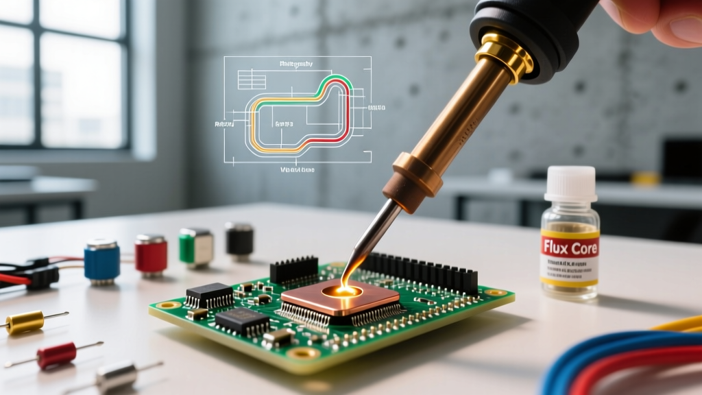
Hand soldering presents a unique thermodynamic challenge: the heat source is localized, and the thermal mass of the component leads acts as a heat sink. You cannot simply set an iron to the alloy's melting point. If SAC305 melts at 217°C, setting your station to 220°C will result in a cold joint because the iron tip will instantly lose its thermal energy upon contact with the copper pad.
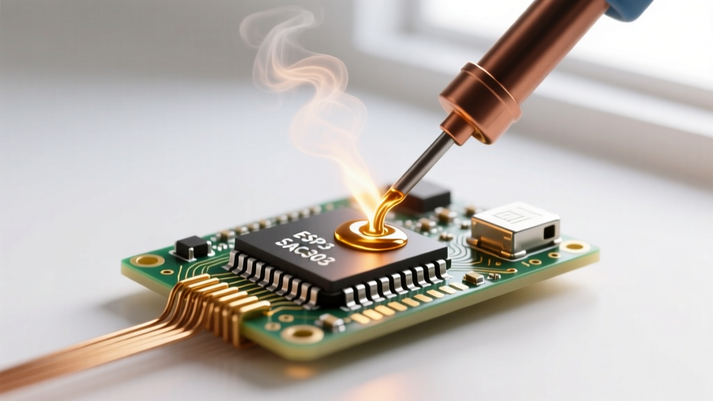
For modern high-efficiency stations like the Hakko FX-951 or the Weller WE1010NA, the optimal lead free soldering temperature for hand work generally falls between 340°C and 360°C. This provides the necessary 'superheat' to transfer energy rapidly into the joint, bringing the localized pad and lead to 230°C+ within 2-3 seconds.
The Danger of the 400°C Crutch
A common mistake among technicians struggling with lead-free wetting is cranking the iron to 400°C+. Material science dictates why this is a destructive practice:
- Flux Carbonization: Modern no-clean fluxes (often based on synthetic resins and weak organic acids) vaporize and carbonize above 380°C. This leaves a hard, glassy residue that actually prevents wetting and is notoriously difficult to clean.
- Tip Oxidation: The iron plating (typically a 100-micron layer of pure iron over copper) oxidizes exponentially faster at 400°C. An oxidized tip loses its thermal transfer coefficient, leading to a vicious cycle of the operator increasing the temperature further.
- Substrate Damage: The localized thermal shock can exceed the Tg (Glass Transition Temperature) of the FR-4 laminate, causing micro-delamination or pad lifting, especially on 2oz copper boards.
Advanced Flux Chemistry and Thermal Synergy
Temperature does not operate in a vacuum; it is inextricably linked to your flux chemistry. As detailed in technical resources from manufacturers like Indium Corporation, the activation temperature of the flux must align with your thermal profile.
If you are using a Rosin Mildly Activated (RMA) or a modern Halogen-Free No-Clean (ROL0) flux, the activators (usually dicarboxylic acids like adipic or succinic acid) require a minimum of 140°C to begin reducing copper oxides. If your hand soldering technique involves applying flux, then immediately touching the iron to the joint before the flux has reached activation temperature, the solder will ball up and refuse to wet. The correct sequence is: apply heat to the substrate, introduce the solder wire (which contains the internal flux core), and allow the flux to boil and clean the surface before the molten alloy flows.
Troubleshooting Thermal Failure Modes
By examining the physical joint, a trained eye can reverse-engineer the thermal profile applied during assembly:
- Dull, Grainy, or Matte Finish: Often indicates a disturbed joint during the pasty range, or excessive Cu3Sn IMC growth due to prolonged heat exposure. (Note: Some modern SAC alloys with bismuth or nickel additions naturally have a matte finish, but traditional SAC305 should be shiny).
- Solder Balling / Dewetting: The lead free soldering temperature was too low, or the dwell time was too short, failing to activate the flux or overcome the liquid-gas surface tension.
- Charred Flux Residue: Iron temperature exceeded 380°C, or the tip was left on the joint for longer than 4 seconds, destroying the flux's oxygen-barrier properties and causing secondary oxidation.
- Cratering (Pad Lift): Extreme thermal shock. The Z-axis expansion of the PCB laminate pushed the copper pad away from the fiberglass matrix due to an excessively high iron temperature applied to a small thermal mass pad.
Conclusion
Mastering lead free soldering temperature is not about memorizing a single number; it is about managing thermal energy transfer, understanding phase diagrams, and respecting the kinetics of intermetallic growth. By aligning your equipment settings—whether a 10-zone reflow oven or a precision micro-soldering iron—with the material science of SAC alloys and modern flux chemistries, you ensure joints that meet the rigorous reliability demands of 2026's high-density electronic assemblies. For further reading on industry acceptance criteria, consult the Kester Technical Resources library and IPC documentation.