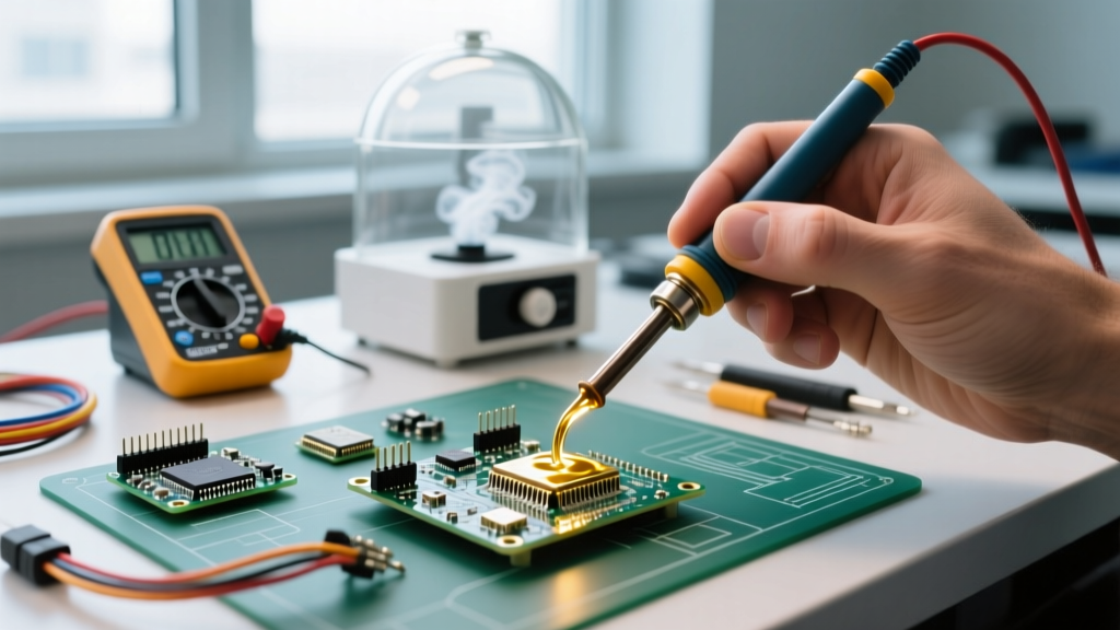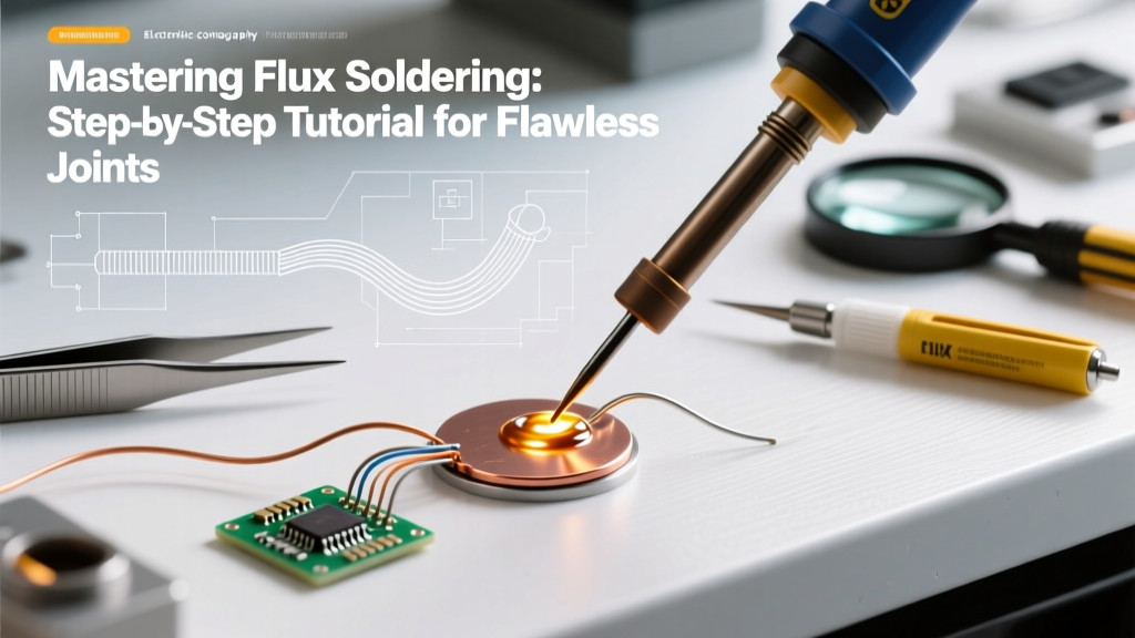

The Metallurgy of Wetting: Why Flux Soldering is a Chemical Process
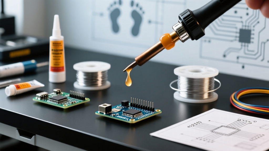
Many beginners treat soldering as a purely thermal process—melting metal to join two surfaces. In reality, flux soldering is a chemical metallurgical process. Without flux, oxygen in the air instantly forms a microscopic layer of copper oxide on your PCB pads and component leads the moment they are heated. Solder will not wet oxidized copper; it will simply ball up and roll off. Flux acts as a chemical reducing agent, stripping away oxides and allowing the molten alloy to form an intermetallic compound (IMC) with the base metals.
According to the IPC Standards for electronic assemblies, proper flux activation and wetting are the primary determinants of joint reliability. In this comprehensive 2026 guide, we will break down the exact chemistry, tools, and step-by-step techniques required to master both through-hole and surface-mount flux soldering.
Decoding Flux Chemistry: Choosing the Right Agent
Before picking up an iron, you must select the correct flux for your specific application. Using the wrong flux can lead to dendritic short circuits, corrosion, or charred, un-wettable pads. Here is how the three primary categories compare in modern electronics workbench environments:
| Flux Category | Base Chemistry | Activation Temp | Residue Profile | Cleaning Requirement |
|---|---|---|---|---|
| Rosin (RMA/RA) | Pine rosin + mild activators | 180°C - 220°C | Hard, amber, non-conductive | Optional (unless RA) |
| No-Clean (NC) | Synthetic resins + halides | 150°C - 200°C | Clear, hard, glass-like | None (if fully heated) |
| Water-Soluble (OA) | Organic acids (lactic/citric) | 120°C - 160°C | Highly active, corrosive | Mandatory (DI water) |
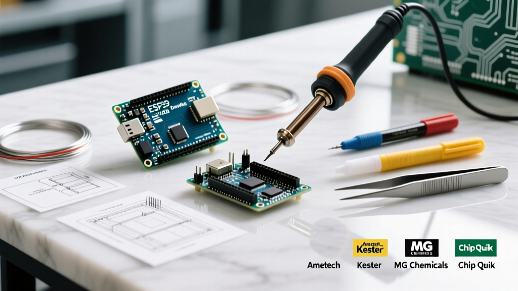
2026 Market Insight: For general bench work, Kester 186 Mildly Activated Rosin remains the gold standard for through-hole components, costing around $14 for a 2oz bottle. For fine-pitch SMD work, synthetic no-clean tacky fluxes like Amtech NC-559-V2-TF ($25–$32 for a 10cc syringe) offer superior viscosity control and prevent component tombstoning.
Essential Tool Loadout for Precision Flux Soldering
To execute the techniques below, you need precise thermal control. Cheap irons with ceramic heaters that lack closed-loop feedback will scorch your flux before the joint reaches wetting temperature.
- Soldering Station: Hakko FX-888D or Weller WE1010 (Set to 320°C for Sn63/Pb37 leaded; 350°C–370°C for SAC305 lead-free).
- Iron Tips: Chisel (2.4mm) for through-hole; Micro-pencil (0.8mm) for SMD drag soldering.
- Flux Applicators: Acid brushes (trim the bristles by half for stiffness) for liquid rosin; precision syringes with 22-gauge blunt needles for SMD paste.
- Wire Solder: 0.8mm diameter Sn63/Pb37 (rosin core) for through-hole; 0.5mm for SMD.
- Flux Remover: 99.9% Isopropyl Alcohol (IPA) and lint-free Kimwipes.
Tutorial 1: Through-Hole Flux Soldering Technique
Even if your solder wire has a rosin core, adding external liquid flux is the secret to achieving the mirror-finish, concave fillets mandated by NASA Workmanship Standards. The internal core often burns off before the heavy thermal mass of a through-hole lead absorbs enough heat.
Step 1: Mechanical Prep and Pre-Tinning
- Clean the PCB pads and component leads with IPA to remove manufacturing oils.
- Insert the component and bend the leads slightly outward to secure it.
- Apply a small drop of Kester 186 liquid flux directly to the pad and lead intersection using a trimmed acid brush.
Step 2: Thermal Transfer and Wetting
- Tin your iron tip with a microscopic amount of fresh solder. This creates a thermal bridge.
- Place the iron tip at a 45-degree angle, simultaneously touching the component lead and the PCB pad. Do not touch the solder wire to the iron yet.
- Count 1 to 2 seconds. You will see the liquid flux bubble and flow—this is the activator stripping the oxides.
Step 3: Feeding and Fillet Formation
- Apply the solder wire to the opposite side of the lead from the iron tip. If the flux did its job, the solder will instantly wick around the lead via capillary action.
- Feed exactly enough solder to form a concave fillet (usually 1–2 seconds of feed time).
- Crucial Sequence: Remove the solder wire first, then remove the iron. Hold the board perfectly still for 3 seconds until the joint solidifies. Moving it during the plastic phase causes a fractured, 'cold' joint.
Tutorial 2: SMD Drag Soldering with No-Clean Flux
Surface mount devices (SMDs), particularly fine-pitch ICs (0.5mm pitch or smaller), require a different approach. Here, we use a high-viscosity tacky flux to hold components in place and manage solder surface tension.
Step 1: Component Tacking
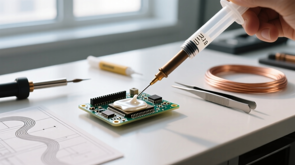
Apply a microscopic dot of Amtech NC-559 no-clean flux to one corner pad. Use tweezers to align the IC, then touch the corner pad with your iron to tack the chip in place. Verify alignment on all four corners under a magnification lamp.
Step 2: Generous Flux Application
Apply a liberal bead of tacky flux across all the pins on one side of the IC. The flux should look like a thick, clear gel covering the pins and pads. Do not be stingy; excess flux prevents bridging.
Step 3: The Drag Technique
- Load your micro-pencil tip with a moderate bead of 0.5mm solder.
- Place the tip at a 45-degree angle to the first pin. Slowly drag the iron across the row of pins. The flux's surface tension will pull the solder off the iron and deposit it exclusively onto the copper pads.
- If a bridge forms between two pins, do not panic and do not use solder wick immediately. Clean your iron tip on a brass sponge, apply a tiny bit more fresh flux, and drag a clean, dry tip over the bridge. The fresh flux will break the surface tension and pull the bridge apart.
Failure Mode Matrix: Troubleshooting Flux Soldering Defects
Even experienced technicians encounter defects when flux dynamics are misunderstood. Use this diagnostic matrix to identify and correct your technique.
| Visual Defect | Root Cause (Flux/Thermal) | Corrective Action |
|---|---|---|
| Charred, Black Residue | Iron temp too high (>380°C) or dwell time exceeded 4 seconds. Flux carbonized, losing chemical activity. | Lower temp to 340°C. Clean with IPA. Reapply fresh flux and reflow quickly. |
| Grainy/Dull Joint | Component moved during the plastic cooling phase, or flux was completely depleted before wetting. | Reheat with fresh flux. Hold board completely still until solder loses its liquid sheen. |
| Solder Balling | Oxide layer too thick; flux failed to activate due to insufficient pre-heat time on the pad. | Apply external liquid flux. Heat pad for 2 full seconds before introducing solder wire. |
| Tacky No-Clean Residue | Insufficient heat applied to the flux. The synthetic resins did not reach full polymerization temperature. | Reflow the joint slightly longer to ensure the flux reaches its full activation and curing threshold. |
Post-Soldering: To Clean or Not to Clean?
The decision to clean flux residue depends entirely on your operating environment and the flux type used. While Kester Flux Technologies and other manufacturers formulate no-clean fluxes to be left on the board, there is a critical caveat: no-clean flux must be fully heated to become inert. If you apply no-clean flux but only partially heat it (common when using a hot air gun for quick rework), the unactivated organic acids remain tacky and can absorb moisture, eventually leading to electrochemical migration (dendrites) and short circuits.
Proper Cleaning Protocol for Rosin and Water-Soluble Fluxes
- Rosin (RMA/RA): Scrub with 99.9% IPA and a stiff-bristled ESD-safe brush. Wipe away the dissolved residue with a lint-free wipe before the IPA evaporates, or the flux will simply redeposit on the board as a sticky white film.
- Water-Soluble (OA): Must be cleaned within 2 to 4 hours of soldering. Use heated (60°C) deionized (DI) water. Tap water contains minerals that will react with the organic acids and cause rapid corrosion. Follow with a compressed air dry or a low-heat oven bake at 80°C for 20 minutes.
Final Thoughts on Process Control
Mastering flux soldering is about respecting the chemical limits of your consumables. By matching your flux chemistry to your thermal profile, maintaining strict dwell times under 3 seconds per IPC guidelines, and understanding the metallurgical purpose of the wetting phase, you will consistently produce aerospace-grade solder joints. Invest in high-quality fluxes, keep your tips clean, and let the chemistry do the heavy lifting.