
The Metallurgical Reality: Why Flux for Electronic Soldering Matters
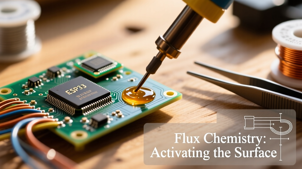
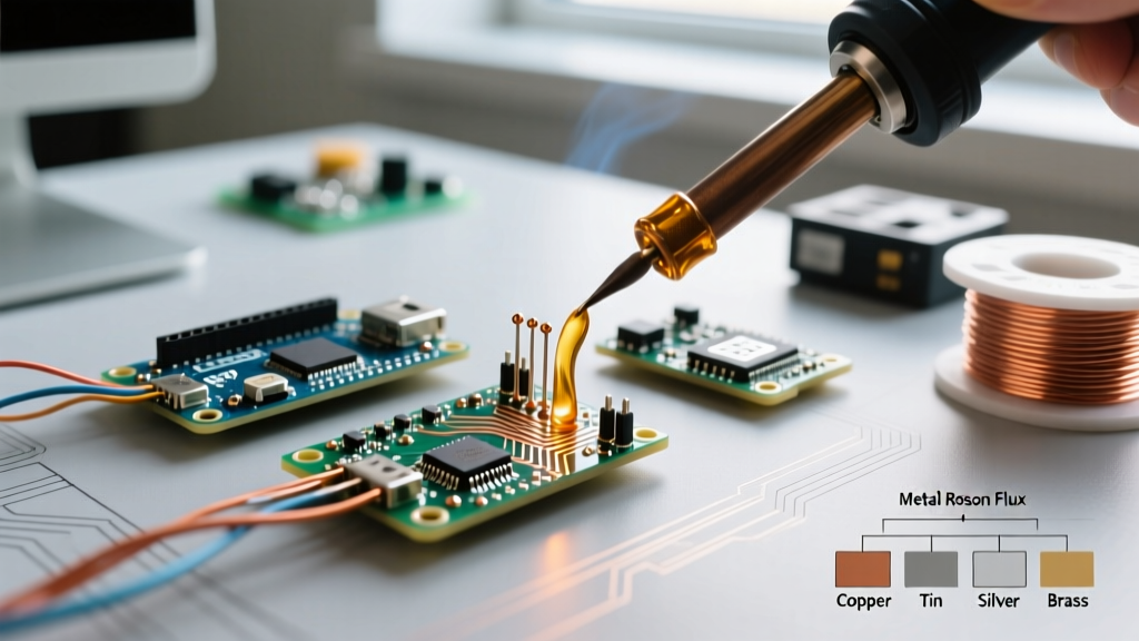
Soldering is frequently misunderstood as a purely thermal process where heat simply melts metal to join two surfaces. In reality, it is a complex chemical and metallurgical reaction. At the core of this reaction is the flux. Without the proper flux for electronic soldering, surface oxides on copper pads and component leads will prevent the molten alloy from wetting the surface, resulting in catastrophic intermetallic bond failures. As of 2026, with the industry's heavy reliance on fine-pitch components like 0201 passives and 0.4mm pitch BGAs, understanding flux chemistry, activation temperatures, and application techniques is no longer optional—it is a strict requirement for reliability.
This comprehensive tutorial will guide you through the exact methodologies for selecting, applying, and cleaning flux in both leaded and lead-free (SAC305, BiSn) PCB assembly environments. We will reference industry benchmarks, including the IPC J-STD-004 standard, to ensure your work meets professional aerospace and consumer electronics criteria.
Decoding Flux Chemistry and IPC Classifications
Before picking up a syringe or brush, you must understand the chemical composition of your consumables. The IPC classifies fluxes using a four-character code (e.g., ROL0, REL1, ORH0). The first two letters denote the base material: RO (Rosin), RE (Resin), OR (Organic Acid), or IN (Inorganic Acid). The third letter indicates activity level: L (Low), M (Medium), or H (High). The final digit represents halide content: 0 (less than 0.05% halides) or 1 (greater than 0.05%).
For modern printed circuit boards, ROL0 (Rosin, Low activity, zero halides) and REL0 (Resin, Low activity, zero halides) are the dominant no-clean formulations. They utilize mild organic activators like adipic or succinic acid, which only become chemically active near 150°C, safely stripping copper oxide just milliseconds before the solder alloy reaches its liquidus state.
Flux Selection Matrix for PCB Assembly
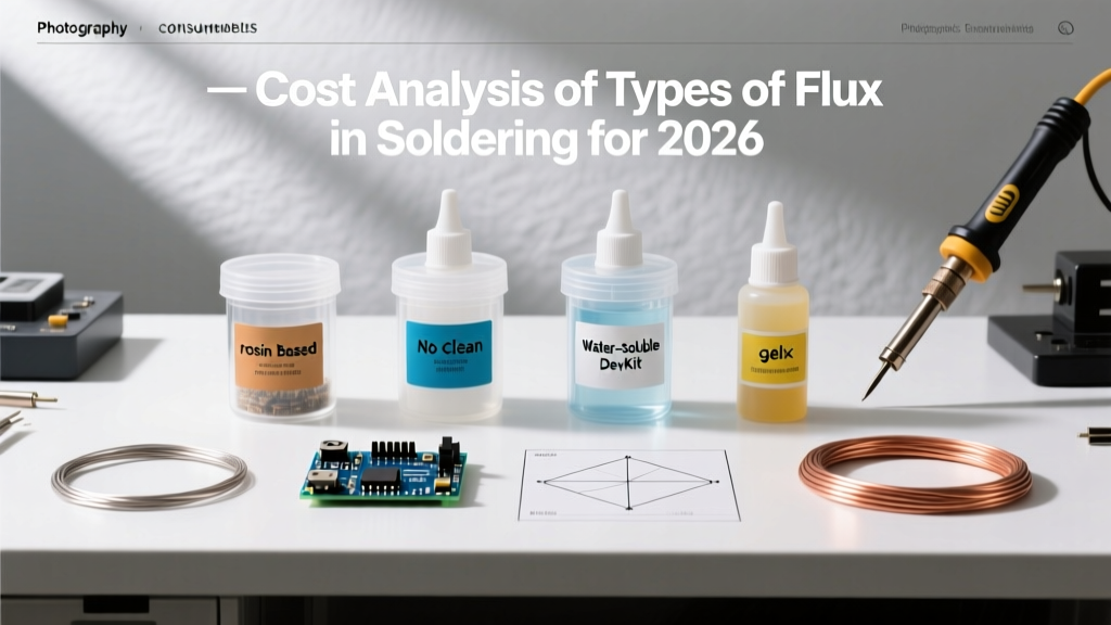
| Flux Category | IPC Type Example | Market Product Reference | Approx. Cost (2026) | Post-Solder Cleaning | Best Application Scenario |
|---|---|---|---|---|---|
| No-Clean Tacky | ROL0 / REL0 | Amtech NC-559-V2-TF | $45 - $65 / 10cc | Optional (Cosmetic) | BGA rework, fine-pitch SMD, QFNs |
| Rosin Mildly Activated | RMA (ROL1) | Kester 186 Liquid | $15 - $25 / 100ml | Recommended (IPA) | Through-hole, heavy wire lugging |
| Water-Soluble (OA) | ORH1 | MG Chemicals 8341 | $20 - $30 / 100ml | Mandatory (DI Water) | Power electronics, severe oxidation |
Step-by-Step: How to Apply Flux for Electronic Soldering
Proper application is about volume control and thermal timing. Applying too much flux can cause bridging on fine-pitch ICs, while applying too little results in dry, oxidized joints. Follow this precise workflow.
Step 1: Substrate Preparation and Pre-Heating
Never apply flux to a contaminated board. Finger oils and environmental dust will carbonize under the iron. Clean the target area using 99% Isopropyl Alcohol (IPA) and a lint-free wipe. If you are working on a multi-layer board with heavy ground planes, use a bottom-side PCB preheater set to 100°C - 120°C. This reduces the thermal shock to the flux, preventing it from boiling and splattering when the iron makes contact.
Step 2: Selecting the Delivery Mechanism
The physical form of your flux dictates your application method:
- Flux Pens (e.g., Chip Quik SMD291AX): Ideal for broad application over SOP or TSSOP ICs. Press the nib down to prime, then draw a single, continuous 1mm wide line across the pads. Do not oversaturate.
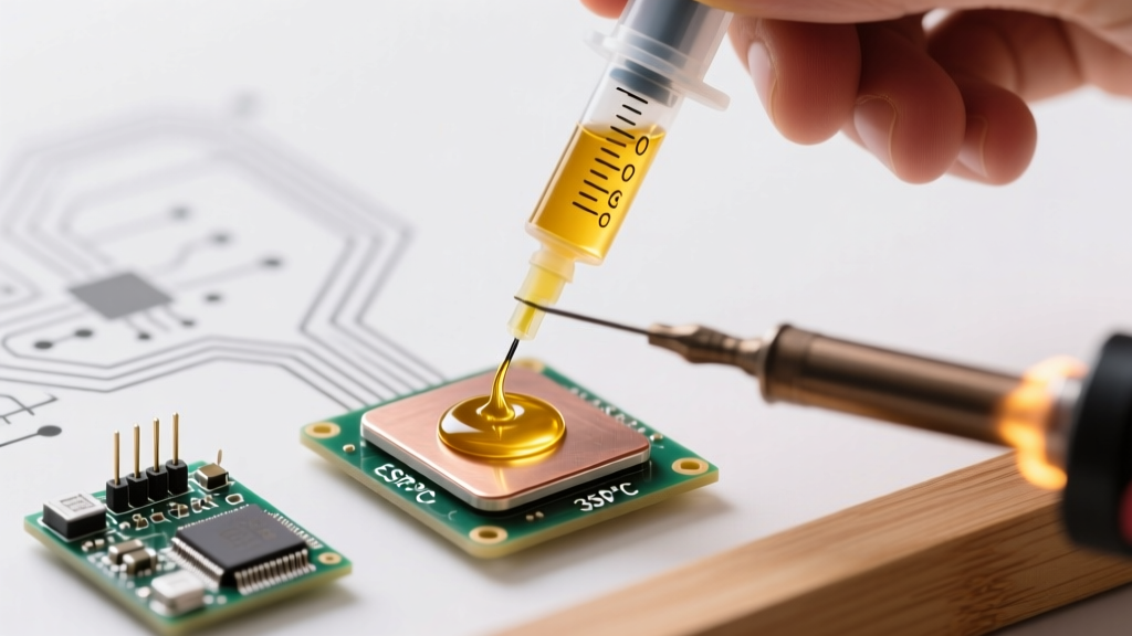
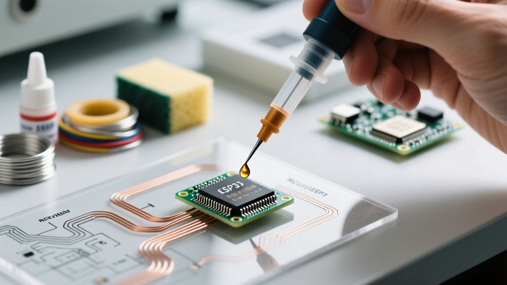
- Syringe Dispensing (Tacky Paste): Mandatory for 0.5mm pitch QFPs and BGAs. Use a 3cc pneumatic or manual syringe fitted with a 22-gauge or 25-gauge blunt-tip stainless steel needle. Apply microscopic dots directly to the corners of the IC footprint, allowing capillary action to pull the flux under the package during reflow.
- Liquid Brush (Rosin): Best for large through-hole connectors. Use an acid brush (trimmed to 5mm bristle length) to paint a thin, even coat over the barrel and lead.
Step 3: Thermal Activation and Soldering
Flux must reach its activation temperature before the solder melts. For standard ROL0 no-clean fluxes, activation begins around 150°C. If you are using a lead-free SAC305 alloy (melting point 217°C), set your iron to 385°C (725°F). If using Sn63/Pb37 (melting point 183°C), set the iron to 350°C (662°F).
- Touch the tinned tip of your iron to the pad and component lead simultaneously.
- Hold for 1.5 to 2 seconds to allow the flux to outgas and strip the oxides. You will see a slight wisp of white smoke—this is the activator vaporizing.
- Feed the solder wire to the joint, not the iron tip. The solder should flash and flow instantly via capillary action.
- Remove the iron within 3 seconds. Prolonged dwell times (over 4 seconds) will burn the flux residue into a hard, black carbon crust that is highly corrosive and impossible to clean without abrasive scraping.
Expert Warning: Never use plumbing paste flux (zinc chloride base) on PCBs. According to guidelines published by NASA Electronic Parts and Packaging (NEPP), inorganic acid fluxes will cause rapid electrochemical migration and dendritic growth, destroying the circuit within weeks of deployment.
Troubleshooting Common Flux Application Failures
Even experienced technicians encounter metallurgical anomalies. Here is how to diagnose flux-related defects based on visual inspection.
1. Solder Balling and Splatter
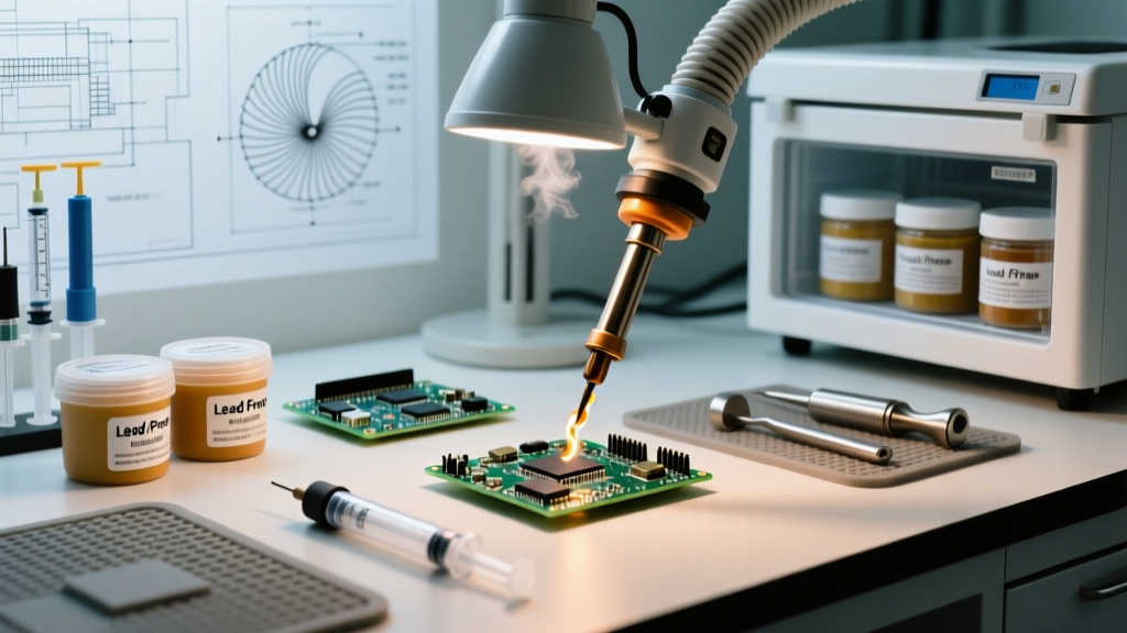
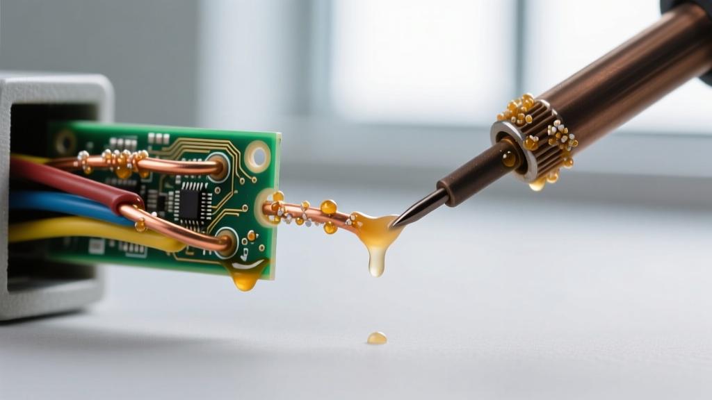
The Symptom: Tiny spheres of solder scatter across the solder mask surrounding the pad. The Cause: Moisture trapped in the flux or rapid thermal shock causing the flux solvents to boil explosively. The Fix: Store your tacky flux syringes in a climate-controlled environment, not a refrigerator (which introduces condensation). If using liquid flux, allow the solvent carrier to flash off for 10 seconds before applying the iron.
2. De-wetting and Solder Pull-Back
The Symptom: The solder clings to the iron tip and pulls away from the pad, leaving a dull, uneven meniscus. The Cause: Flux exhaustion. The pad was heavily oxidized, and the mild activators in the no-clean flux were consumed before the solder could wet the copper. The Fix: Switch to a more aggressive RMA (Rosin Mildly Activated) liquid flux for the initial tinning phase, clean with IPA, and then proceed with your standard no-clean solder wire.
3. White Chalky Residue
The Symptom: A crusty white ring forms around the solder joint after cooling. The Cause: Incomplete activation or moisture reacting with the rosin acids, creating metallic salts. The Fix: This is purely cosmetic for ROL0 fluxes and does not affect reliability. However, if optical inspection requires a clean board, wash the area using 99% IPA and a stiff hog-hair brush, followed by a compressed air blast to displace the solvent.
Post-Solder Cleaning Protocols
While 'no-clean' fluxes are designed to remain on the board, there are scenarios where cleaning is mandatory. If you are applying a conformal coating (e.g., acrylic or urethane) or operating in a high-humidity environment, residual flux can interfere with coating adhesion or cause parasitic leakage currents.
For Rosin and No-Clean fluxes, use an automated ultrasonic cleaner filled with a specialized saponifier (like Kester 2000 at a 5% dilution ratio) heated to 50°C, followed by a pure IPA rinse. For Water-Soluble (OA) fluxes, cleaning is non-negotiable. You must wash the PCB with heated Deionized (DI) water (minimum 18 megohm-cm resistivity) within 2 hours of soldering. Failure to clean water-soluble flux will result in severe galvanic corrosion of the copper traces. For further validation on cleaning standards, consult the technical resources provided by major manufacturers like Kester to ensure your specific alloy and flux combination meets long-term reliability metrics.
Mastering the application of flux for electronic soldering transforms your work from amateur wire-tacking to professional-grade metallurgical bonding. By respecting the chemistry, controlling your thermal profiles, and utilizing precision delivery tools, you guarantee the electrical and mechanical integrity of every joint you create.