
The Chemistry of the Joint: Why Application Matters
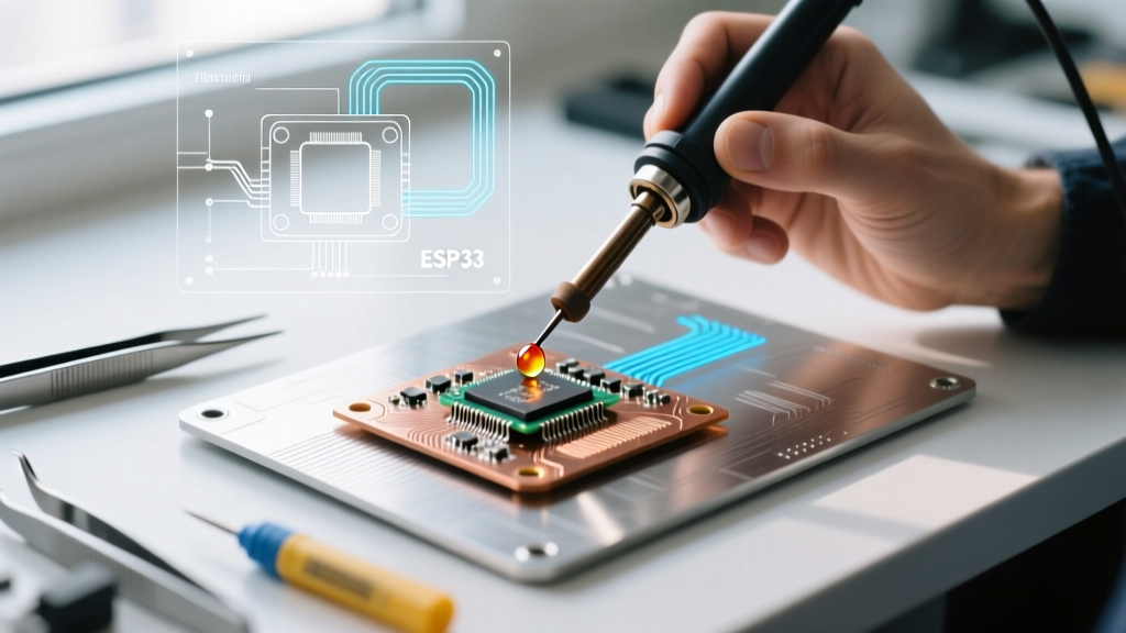
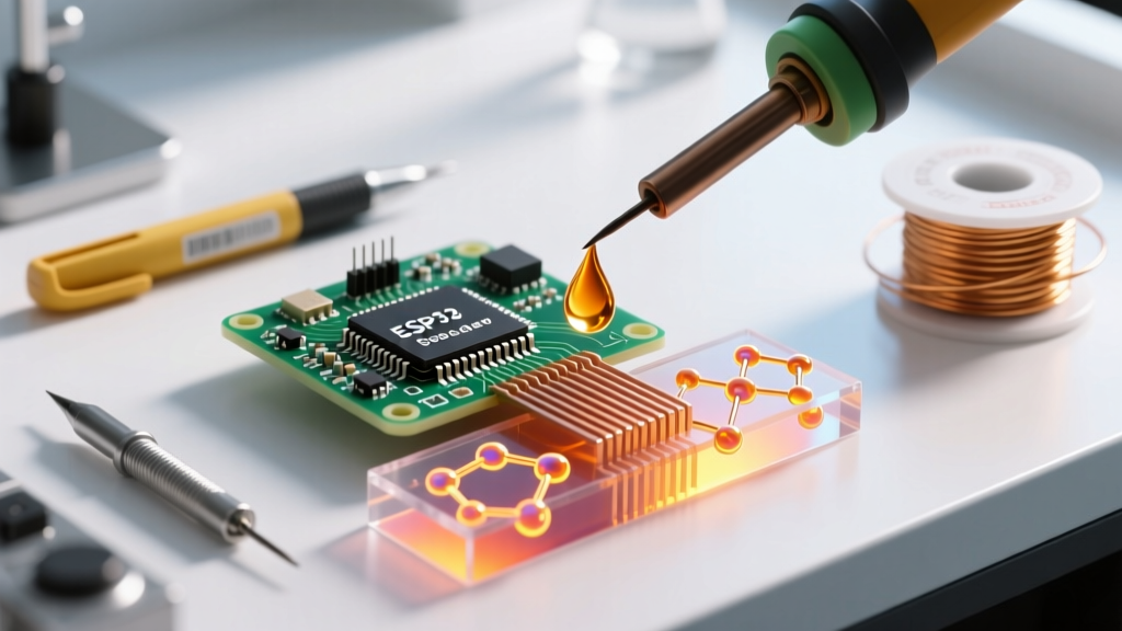
Understanding how to apply soldering flux correctly is the dividing line between a reliable, shiny fillet and a cold, high-resistance joint. Flux is not merely a cleaning agent; it is a complex chemical catalyst designed to reduce metal oxides, lower the surface tension of molten solder, and prevent re-oxidation during the thermal cycle. As of 2026, with the industry standard pushing toward miniaturized 01005 and 008004 surface-mount components, the precision of flux application has become just as critical as the solder alloy itself.
According to the NASA Workmanship Standard for Soldered Electrical Connections, insufficient flux coverage leads to incomplete wetting, while excessive flux can cause parasitic capacitance or electrochemical migration (dendritic growth) if left uncleaned. This guide breaks down the exact methodologies for applying different flux chemistries, ensuring you select the right tool and technique for your specific electronics assembly or rework scenario.
Expert Insight: Flux activation is temperature-dependent. Most rosin-based fluxes begin activating around 120°C and peak between 180°C and 220°C. Applying flux to a joint that is already above 250°C will cause the solvents to flash-boil, resulting in dangerous spattering and immediate thermal degradation of the flux's active agents.
Flux Types and Application Tool Selection Matrix
Selecting the correct application method depends entirely on the flux chemistry and the physical topology of the joint. Below is a decision matrix for matching flux types to their optimal delivery systems.
| Flux Chemistry | Common Form Factor | Optimal Application Tool | Best Use Case | Approx. Cost (2026) |
|---|---|---|---|---|
| Rosin Mildly Activated (RMA) | Liquid / Paste | Bristle Brush or Flux Pen | Through-hole, heavy wire, general PCB rework | $8 - $18 |
| No-Clean (NC) | Liquid / Gel | Micro-Pen or Precision Syringe | SMD rework, QFN/BGA reflow, fine-pitch PCB | $12 - $35 |
| Water-Soluble (OA) | Liquid | Aerosol Spray or Pump Bottle | Automated wave soldering, heavy oxidation removal | $20 - $40 |
| Tack Flux (Syringe) | Thixotropic Gel | Syringe with 20-27G Needle | BGA reballing, micro-SMD placement | $25 - $55 |
Step-by-Step Application Techniques by Tool
1. The Flux Pen: Precision Through-Hole and SMD Rework
Flux pens, such as the widely used MG Chemicals 8341 No-Clean Flux Pen ($10-$14), are ideal for targeted application on standard SMD pads and through-hole leads. The porous nib regulates flow, preventing the flooding of adjacent vias or components.
- Preparation: Shake the pen vigorously for 15 seconds until the internal agitator clicks. Prime the nib on a scrap piece of FR4 or cardboard until the fluid saturates the tip.
- Application: Hold the pen at a 45-degree angle. Apply a thin, uniform bead directly over the target pads. For an SOIC-8 chip, draw a single continuous line across the pads, extending roughly 1mm beyond the outer pins.
- Thermal Timing: Allow the solvent (usually isopropanol or a proprietary glycol ether) to evaporate for 3 to 5 seconds before introducing the soldering iron. This prevents the tip from hydroplaning on boiling solvent.
2. Syringe and Blunt Needle: Tack Flux for BGA and Micro-SMD
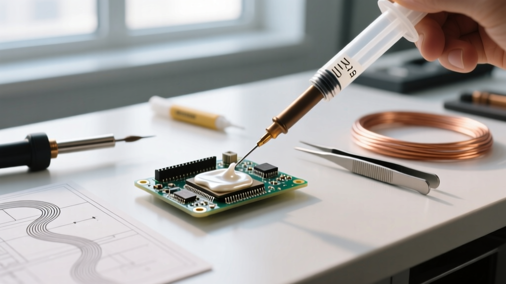
When dealing with bottom-termination components (BTCs) like QFNs or BGAs, liquid flux will wick under the component and potentially cause voiding during reflow. Instead, use a high-viscosity tack flux like Amtech NC-559-V2-TF ($30-$45 per 10cc syringe).
- Needle Selection: Use a 22-gauge or 25-gauge stainless steel blunt tip. Avoid plastic tips, as they can deform under thumb pressure, resulting in unpredictable dispensing volumes.
- Dispensing Technique: Apply a small 'X' or a single dot in the center of the component footprint. The surface tension of the molten solder and the flux's capillary action will pull the alloy under the BGA during the reflow profile.
- Volume Control: For a 5x5mm QFN, a single hemisphere of flux roughly 2mm in diameter is sufficient. Over-application will cause the flux to boil out the sides, leaving sticky, difficult-to-clean residues that can interfere with automated optical inspection (AOI).
3. Bristle Brush and Paste: Heavy Wire and Terminal Lugs
For high-current applications, large gauge wires (e.g., 10 AWG to 4 AWG), and mechanical terminal lugs, liquid flux is inadequate due to the high thermal mass of the joint. You need a heavy-bodied rosin paste like Kester 186 RMA Paste ($12-$20 per tin).
- Pre-Tinning: Strip the wire and mechanically clean it with 400-grit abrasive if heavily oxidized. Dip the bare wire directly into the paste flux tin, ensuring 360-degree coverage.
- Heat Transfer: Apply the iron tip to the wire, not the flux. The heat will melt the paste, allowing it to penetrate the individual copper strands via capillary action.
- Feed Solder: Introduce 63/37 or Sn96.5/Sn3.0/Ag0.5 solder wire into the joint. The Kester 186 will blister and smoke as the rosin activates, leaving a bright, fully wetted tinned wire.
Critical Failure Modes: How Application Goes Wrong
Even experienced technicians fall into bad habits when applying flux. Recognizing these failure modes is essential for maintaining IPC-A-610 Class 3 reliability standards.
Failure Mode A: Thermal Shock from Cold Flux
Applying room-temperature liquid flux directly onto a joint that is already being heated by a 380°C iron causes instantaneous thermal shock. This can crack ceramic capacitors (MLCCs) and delaminate the copper pads from the FR4 substrate. Correction: Always apply flux to a cold joint, or use a low-thermal-mass hot air pencil to warm the board to 80°C before liquid flux application.
Failure Mode B: The 'Drowned' Pad
Flooding a fine-pitch 0.5mm QFP footprint with liquid flux creates a surface tension barrier. When the solder melts, it cannot displace the massive volume of liquid flux, resulting in non-wetting or massive solder bridging between adjacent pins. Correction: Use the 'dip and touch' method—dip a fine-tipped brush or toothpick into the flux bottle, then touch it to the pad, transferring only a micro-drop.
Failure Mode C: Acid Flux Contamination
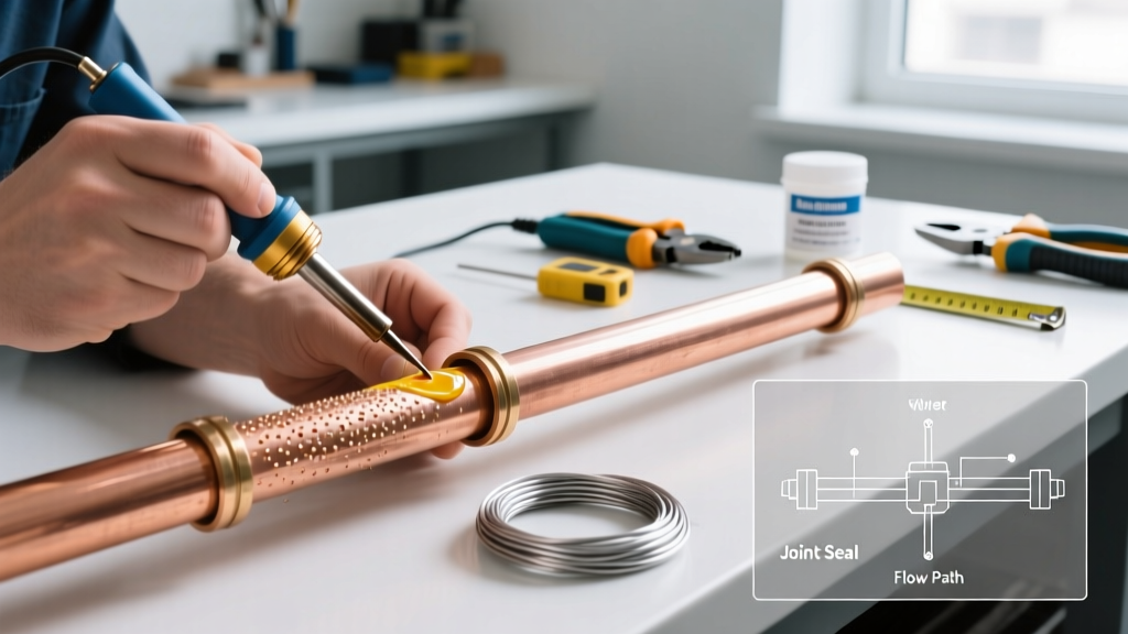
Using plumbing flux (which contains highly corrosive zinc chloride or ammonium chloride) on PCB electronics. This will cause rapid galvanic corrosion, eating through the copper traces within weeks and creating conductive dendrites that short the circuit. Correction: Strictly segregate plumbing and electronics workspaces. Only use fluxes compliant with IPC J-STD-004B for electronic assemblies.
Post-Soldering: Cleaning Requirements by Flux Type
How you apply flux dictates how you must clean it. Residue left on a high-impedance analog circuit can alter signal paths, while residue on a high-voltage power supply can cause arcing.
| Flux Type | Residue Conductivity | Corrosivity | Mandatory Cleaning Solvent | IPC Standard Reference |
|---|---|---|---|---|
| Pure Rosin (R) | Non-Conductive | Non-Corrosive | Optional (Isopropanol for aesthetics) | IPC J-STD-001 |
| No-Clean (NC) | Low (under normal conditions) | Very Low | Specialized saponifiers if required | IPC J-STD-004B |
| RMA / RA | Moderate | Mild | 99% IPA, HFE solvents, or ultrasonic | IPC J-STD-001 |
| Water-Soluble (OA) | Highly Conductive | Highly Corrosive | Deionized (DI) Water + Saponifier | IPC J-STD-001 |
Expert FAQ: Edge Cases in Flux Application
Can I mix different flux types on the same board?
It is highly discouraged. Mixing a water-soluble (OA) flux with a no-clean flux can cause a chemical reaction that renders both fluxes inactive and creates a highly corrosive, gum-like residue that is nearly impossible to clean. Stick to one chemistry per assembly. For rework on a no-clean board, use a no-clean rework flux like Chip Quik SMD291AX.
How do I apply flux to the inside of a shielded RF can?
Shielded RF cavities trap heat and are highly sensitive to dielectric changes. Do not use liquid flux, as the solvents will pool in the corners and outgas during operation, potentially contaminating sensitive RF oscillators. Instead, use a minimal amount of no-clean gel flux applied via a 27-gauge needle strictly to the grounding pads before placing the shield.
Why does my flux turn black and burn when I apply it?
This indicates thermal degradation. Your soldering iron temperature is likely set too high (above 400°C), or you are dwelling on the joint for too long. Modern lead-free SAC305 alloys require a tip temperature of 350°C to 370°C. If the flux chars instantly upon contact, lower your iron temperature, use a larger chisel tip to increase thermal transfer efficiency, or switch to a high-temperature synthetic flux formulated for lead-free processes, such as Kester's LF-Series.
Final Thoughts on Flux Mastery
Mastering how to apply soldering flux is less about the physical motion and more about understanding the thermal and chemical environment of your specific joint. By matching the flux chemistry to the correct application tool—and respecting the activation temperatures of the rosin or synthetic activators—you will consistently produce IPC-compliant, mechanically robust, and electrically flawless solder joints. Always prioritize precision over volume; a micro-drop of the right flux will always outperform a flood of the wrong one.