
The Thermodynamics of the Solder Joint
When builders and engineers ask, 'what temperature for soldering,' the answer is never a single static number. Soldering is a dynamic thermal transfer process. The temperature displayed on your station's dial is not the temperature of the joint; it is the idle temperature of the tip. To form a reliable intermetallic compound (IMC), the actual joint must reach the alloy's liquidus temperature and maintain it for a specific dwell time. As of 2026, with the industry's mass adoption of ultra-fine 0201 and 01005 SMD components alongside heavy-duty power electronics, understanding material-specific thermal profiles is the dividing line between a reliable connection and a catastrophic field failure.
According to foundational guidelines outlined in SparkFun's soldering tutorials and broader IPC workmanship standards, the general rule of thumb is to set your iron 30°C to 50°C above the liquidus (melting) point of the solder alloy. However, this delta shifts dramatically based on the thermal mass of the substrate, the gauge of the wire, and the specific flux chemistry being utilized.
Material Compatibility Matrix: Alloys & Temperatures
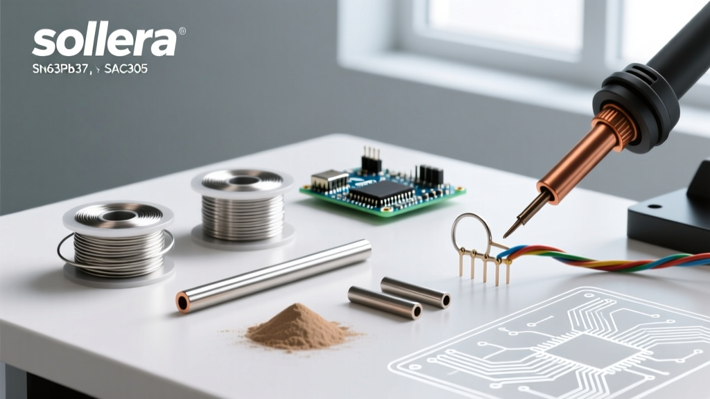
Different metallurgical compositions require vastly different thermal inputs. Below is a comprehensive compatibility matrix for the most common alloys used in modern electronics and DIY fabrication.
| Alloy Composition | Common Name | Liquidus Temp | Ideal Iron Temp | Max Dwell Time | Best Application |
|---|---|---|---|---|---|
| Sn63 / Pb37 | Eutectic Leaded | 183°C (361°F) | 300°C - 330°C | 2.0 - 3.0s | Prototyping, DIY, vintage repair |
| SAC305 (Sn96.5/Ag3.0/Cu0.5) | Standard Lead-Free | 217°C - 220°C | 350°C - 380°C | 1.5 - 2.5s | Commercial PCB assembly, RoHS |
| Sn96.5 / Ag3.5 | Silver-bearing | 221°C (430°F) | 360°C - 390°C | 1.5 - 2.5s | High-reliability, automotive |
| Sn42 / Bi57.6 | Low-Temp Bismuth | 138°C (280°F) | 200°C - 230°C | 1.0 - 2.0s | Heat-sensitive components, flex PCBs |
| Sn95 / Sb5 | High-Temp Antimony | 232°C - 240°C | 380°C - 410°C | 2.0 - 4.0s | High-heat environments, power stages |
Leaded vs. Lead-Free: The Thermal Delta
The transition from Sn63/Pb37 to SAC305 remains the most common hurdle for hobbyists. SAC305 requires significantly higher thermal input. If you attempt to solder a heavy ground plane using SAC305 at 320°C, the tip will instantly lose its heat to the copper, resulting in a dull, grainy cold joint. You must increase the station temperature to at least 360°C and use a chisel tip to maximize surface area contact.
Low-Temperature Bismuth Alloys
Bismuth-based alloys like Sn42/Bi57.6 are gaining massive traction in 2026 for repairing flexible printed circuits (FPCs) and heat-sensitive sensors. Because the liquidus point is only 138°C, setting your iron above 240°C will cause rapid flux burnout and potential delamination of the polyimide substrate. Always use a dedicated, thoroughly cleaned tip for bismuth alloys to prevent cross-contamination with lead-free solder, which creates a brittle, low-melting-point ternary eutectic that fails under minor mechanical vibration.
Substrate Sensitivity: PCBs and Wire Gauges
The material you are soldering to dictates the upper thermal limits just as much as the solder itself.
- Standard FR-4 PCBs: The glass transition temperature (Tg) of standard FR-4 is typically 130°C to 140°C, while high-Tg boards handle up to 170°C. Prolonged exposure to iron temperatures above 380°C for more than 5 seconds will cause the copper pads to lift and the epoxy resin to decompose, releasing toxic fumes and destroying the via barrel.
- Polyimide (Flex) Circuits: Extremely sensitive to localized heat. Iron temperatures should rarely exceed 300°C, and dwell times must be kept under 1.5 seconds. Using a low-thermal-mass micro-pencil tip is mandatory here.
- Copper Wire (AWG): Wire acts as a massive heat sink. When soldering 12 AWG silicone wire to a thick XT60 connector, a standard 60W iron will fail. You need a high-wattage station (100W+) set to 400°C with a heavy bevel tip to push enough joules into the copper to melt the solder without melting the wire's insulation further up the line.
The Hidden Variable: Tip Geometry and Thermal Mass
Answering 'what temperature for soldering' is incomplete without addressing tip geometry. A conical tip set to 400°C will transfer less heat to a joint than a wide chisel tip set to 320°C. This is due to the contact surface area and the thermal mass of the copper core inside the tip.
Pro-Tip: Never compensate for a tip that is too small by simply turning up the heat dial. This leads to oxidized tips, burned flux, and damaged pads. Instead, match the tip geometry to the pad size, and let the station's thermal recovery do the work.
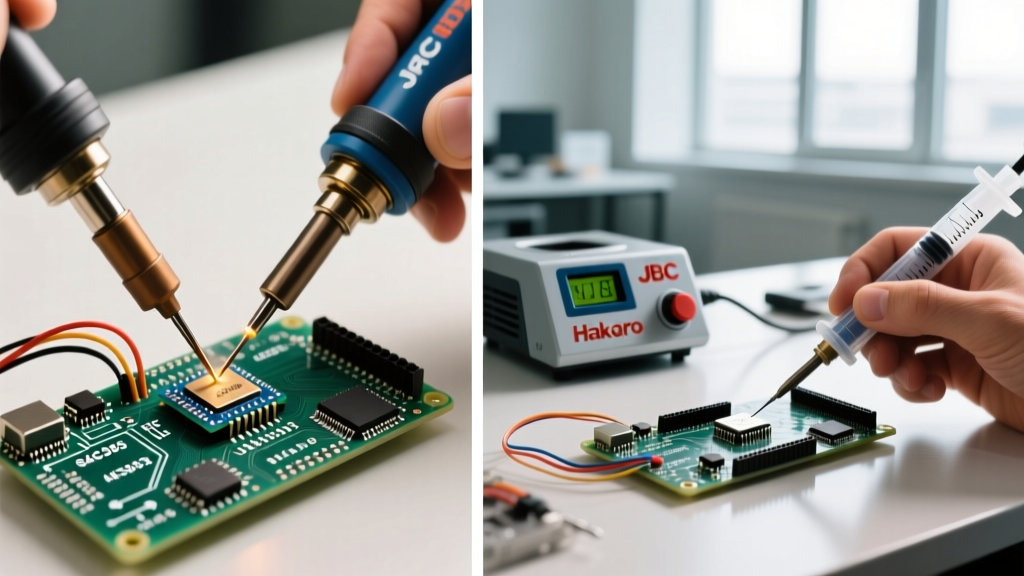
Modern stations handle thermal recovery differently. Entry-level USB-C irons like the Pinecil V2 (retailing around $26) use RISC-V processors to drive rapid PID heating, but their lightweight tips lack the raw thermal mass for heavy ground planes. Mid-range workhorses like the Hakko FX-888D (~$110) offer excellent T18 tip compatibility for general DIY. However, for demanding multi-layer PCBs and heavy wire, active-tip systems like the JBC CD-2BQE (~$580) place the heating element microns from the pad, allowing you to actually lower your dial temperature by 30°C while achieving instantaneous joint wetting.
Flux Activation and Thermal Degradation
Flux is the chemical cleaner that removes oxidation, allowing the molten alloy to form an intermetallic bond. Every flux chemistry has a specific activation and degradation temperature window.
- Rosin Mildly Activated (RMA): Activates around 150°C. If your iron is set too low, the flux will melt but fail to clean the oxides. If set above 380°C, the rosin carbonizes, turning into a hard, black, mildly corrosive shell that traps voids inside the joint.
- No-Clean (NC): Highly sensitive to thermal overshoot. Designed to leave a benign residue, but if subjected to excessive heat or prolonged dwell times, the residue can become conductive or corrosive over time, leading to electrochemical migration (dendrite growth) in humid environments.
- Water-Soluble (OA): Contains aggressive organic acids. It requires precise temperature control; if the joint is not heated rapidly and cleaned properly post-soldering, the active acids will rapidly etch the copper traces.
Troubleshooting Thermal Failures
Use this diagnostic guide to adjust your thermal profile based on visual and physical joint feedback:
- Dull, Grainy, or Bulky Joints: The temperature is too low, or the thermal mass of the tip is insufficient. The solder cooled before the IMC layer could properly form. Fix: Increase temp by 20°C or switch to a wider chisel tip.
- Solder Balls Up and Refuses to Wet: The tip is oxidized from running too hot, or the flux has burned off before the solder flowed. Fix: Lower the idle temperature, re-tin the tip, and apply fresh external flux.
- Pad Lifting or Discoloration: Severe thermal overstress. The localized temperature exceeded the substrate's decomposition threshold. Fix: Lower the temperature, use a more aggressive flux to speed up wetting, and reduce dwell time.
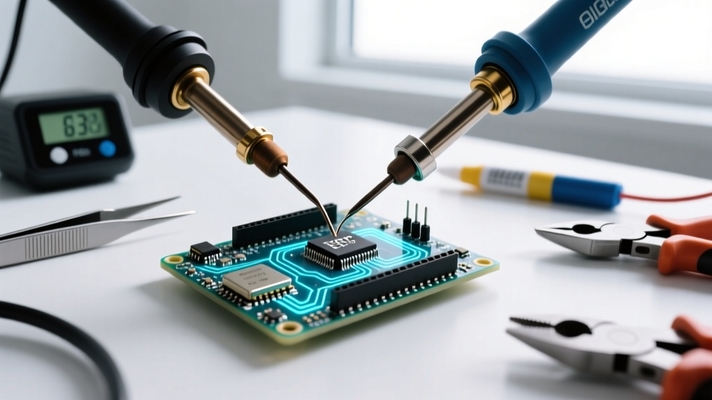
- Pitting and Cratering: Often seen in lead-free BGA or QFN rework when the heat is applied unevenly, causing localized thermal expansion that cracks the copper pad from the laminate. Fix: Use pre-heating (bottom heat) to bring the entire board to 120°C before applying top heat.
Frequently Asked Questions
What temperature for soldering standard DIY electronics?
For general through-hole and basic SMD work using Sn63/Pb37 leaded solder, set your station between 300°C and 320°C (572°F - 608°F). This provides enough thermal headroom to melt the solder in 2 seconds without risking damage to standard FR-4 boards or plastic component housings.
Why does my solder melt but stick to the iron instead of the pad?
This is a classic wetting failure caused by a temperature mismatch and flux burnout. The pad is too cold to accept the solder, while the iron is hot enough to melt it. The flux boils off the iron instantly, leaving the solder oxidized. Apply liquid flux directly to the pad, ensure your tip is clean and tinned, and verify your iron is set to at least 330°C for leaded applications.
Can I use the same temperature for wires and PCBs?
No. Wires, especially thick stranded copper, act as massive heat sinks. While a PCB pad might require 320°C, soldering a 10 AWG wire to a heavy terminal may require pushing a high-wattage station to 380°C or 400°C with a heavy bevel tip to achieve the necessary thermal transfer before the wire insulation melts.