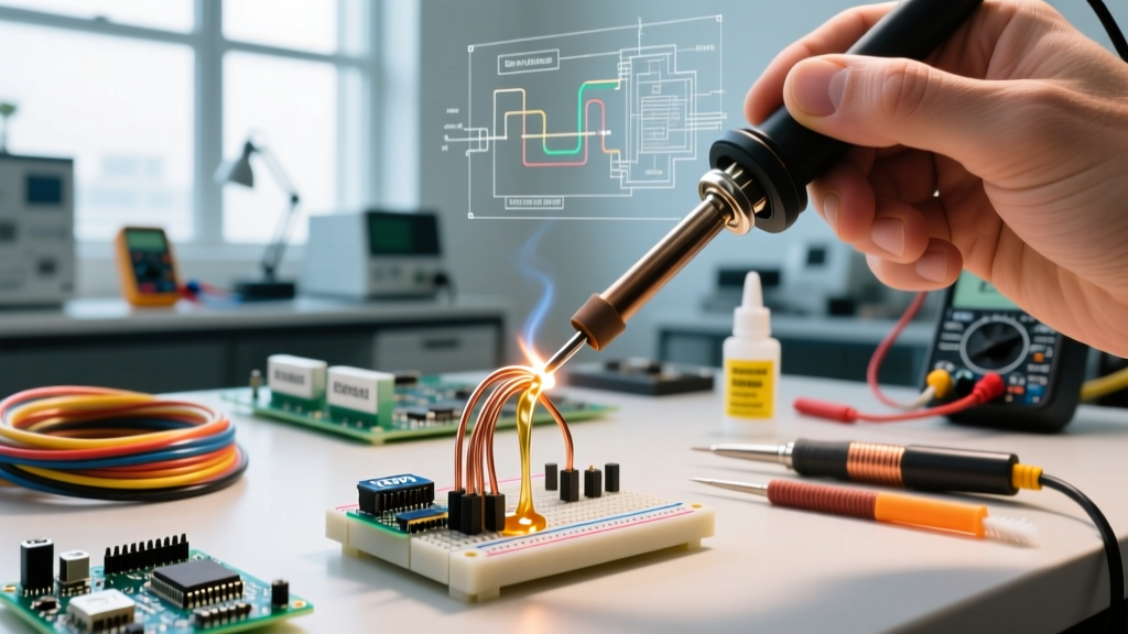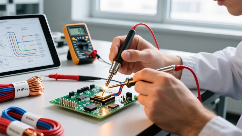

The Critical Role of Jumper Soldering in High-Reliability Manufacturing
In the realm of consumer electronics, jumper wires are often associated with hobbyist breadboarding or quick prototyping. However, in industrial manufacturing, aerospace, and medical device production, jumper soldering is a highly regulated, mission-critical process. Engineering Change Orders (ECOs), late-stage design modifications, and the repair of high-value multilayer printed circuit boards (PCBs) frequently require the installation of hard-wired jumpers. When performed on IPC Class 3 high-reliability assemblies, jumper soldering demands strict adherence to material specifications, thermal profiling, and mechanical securing protocols to ensure long-term operational stability under extreme environmental stress.
Material Selection: Wire Insulation and Conductor Specifications
The foundation of a reliable jumper connection lies in the wire selection. Industrial applications prohibit the use of standard PVC-insulated hookup wire due to its low melting point and outgassing properties. Instead, high-performance fluoropolymers and polyimides are mandated.
| Insulation Material | Max Operating Temp | Dielectric Strength | Primary Industrial Application | Approx. Cost (per 100ft spool, 28 AWG) |
|---|---|---|---|---|
| PTFE (Teflon) | 200°C | High | Aerospace, high-temp reflow zones | $45 - $65 |
| Kapton (Polyimide) | 250°C+ | Very High | Medical, high-density routing | $85 - $110 |
| FEP (Fluorinated Ethylene) | 150°C | High | Automotive ECUs, general Class 3 | $35 - $50 |
| ETFE (Tefzel) | 150°C | Moderate-High | Ruggedized military harnesses | $55 - $75 |
For conductor specifications, silver-plated copper wire in the 28 AWG to 32 AWG range is the industry standard. Silver plating prevents oxidation during storage and improves wetting characteristics when using lead-free alloys like SAC305 (Sn96.5Ag3.0Cu0.5). Brands like Alpha Wire (e.g., the 1551 series) and Belden provide the tight-tolerance extrusions required for automated thermal stripping.
IPC and NASA Standards for Jumper Routing
Industrial jumper soldering is governed primarily by IPC-7711/21B (Rework, Modification and Repair of Electronic Assemblies) and, for space-grade hardware, NASA-STD-8739.3. According to guidelines published by the NASA Electronic Parts and Packaging (NEPP) Program, jumper routing must never compromise the structural integrity of the PCB or create electromagnetic interference (EMI) loops.
IPC Class 3 Routing Mandates: Jumper wires must be routed point-to-point with minimal length. They must not cross over unpopulated pads, vias, or test points. Furthermore, jumpers must maintain a minimum clearance of 0.5mm from the edges of adjacent components to prevent mechanical stress transfer during thermal cycling.
Tenting and Securing
Jumpers routed over bare copper traces must be insulated from the trace to prevent short circuits. This is typically achieved by applying a secondary layer of Kapton tape or a liquid photoimageable (LPI) solder mask pen. Once routed, the wire cannot simply rely on the solder joints for mechanical support; it must be secured to the PCB substrate using specialized adhesives.
The Professional Jumper Soldering Workflow
Achieving a zero-defect jumper installation requires a systematic approach that eliminates variables. Below is the standard operating procedure (SOP) for a Class 3 rework station in 2026.
- Precision Stripping: Mechanical wire strippers are strictly prohibited for 30+ AWG wire in high-reliability environments, as they risk nicking the conductor, creating a stress riser that will fail under vibration. Thermal strippers, such as the MEISEI ST-101, use a heated blade to melt the insulation and pull it away cleanly, leaving the silver-plated copper pristine.
- Pad Preparation: The target PCB pads are cleaned with high-purity isopropyl alcohol (IPA) and lightly tinned using a low-residue, no-clean flux like Kester 952-S. If the pad features an ENIG (Electroless Nickel Immersion Gold) finish, a brief application of flux is critical to break through the gold layer and allow the solder to bond to the underlying nickel.
- Component Tinning: Both the PCB pad and the stripped end of the jumper wire are pre-tinned. This ensures that the final soldering step requires minimal thermal dwell time, reducing the risk of pad cratering.
- Thermal Soldering: Using a high-thermal-recovery station like the JBC CD-2BQF equipped with a C245-764 micro-spoon tip, the operator bridges the joint. The iron temperature is set to 360°C for SAC305 lead-free alloy, with a maximum dwell time of 2.5 seconds per joint to prevent delamination of the PCB substrate.
- Fillet Inspection: The resulting solder fillet must exhibit a smooth, concave shape with a visible wetting angle of less than 90 degrees, indicating proper intermetallic compound (IMC) formation.
Securing the Jumper: Adhesives and Potting Compounds
Solder joints are designed to conduct electricity, not to act as mechanical hinges. To prevent the jumper wire from vibrating loose or tearing the PCB pad during handling, the wire must be bonded to the board. In modern production lines, UV-curable adhesives are the standard due to their rapid cure times and lack of volatile organic compounds (VOCs).
- Dymax 9-20637-F-LO: A light-curable acrylate adhesive specifically formulated for flexible wire tacking. It cures in seconds under a Dymax BlueWave 200 UV spot lamp and remains slightly flexible to absorb thermal expansion mismatches.
- Henkel Loctite 3526: A high-viscosity, toughened acrylic adhesive used for heavier gauge jumpers (24-26 AWG) that require rigid structural support.
The adhesive is dispensed using a pneumatic syringe (e.g., Nordson EFD Ultimus V) to ensure exact volumetric control, typically applying a 2mm to 3mm bead along the center span of the jumper wire.
Common Failure Modes and Edge Cases in Class 3 Assemblies
Even experienced technicians encounter edge cases during industrial jumper soldering. Recognizing these failure modes is critical for quality assurance.
Capillary Wicking
If the soldering iron is held on the joint too long, or if the wire is not properly heat-sinked, molten solder can wick up the jumper wire beneath the insulation. This creates a rigid, brittle section of wire immediately adjacent to the solder joint. Under mechanical vibration, this rigid-to-flexible transition point becomes a fulcrum, leading to copper fatigue and eventual wire fracture.
Pad Cratering on HDI Boards
High-Density Interconnect (HDI) boards utilize micro-vias and thin dielectric layers. Applying excessive downward pressure or prolonged heat with a high-mass soldering tip can cause the resin in the PCB to expand rapidly, fracturing the barrel of the micro-via or lifting the copper pad entirely from the substrate. This is why active-tip technology (like JBC's cartridge system) is preferred over traditional ceramic heating elements, as it delivers instantaneous heat exactly where needed without requiring excessive physical pressure.
2026 Equipment Cost Matrix for Production Rework Stations
Setting up a dedicated, IPC-compliant jumper soldering and wire prep cell requires a specific capital investment. Below is a breakdown of the essential equipment costs for a professional rework environment in 2026.
| Equipment Category | Specific Model / Brand | Estimated Cost (USD) | Justification |
|---|---|---|---|
| Thermal Wire Stripper | MEISEI ST-101 | $480 | Prevents conductor nicking on 30+ AWG wire. |
| Precision Soldering Station | JBC CD-2BQF + C245-764 Tip | $695 | Sub-second thermal recovery for lead-free alloys. |
| UV Curing Spot Lamp | Dymax BlueWave 200 | $3,450 | Rapid, localized curing of wire-tacking adhesives. |
| Pneumatic Dispenser | Nordson EFD Ultimus V | $1,800 | Repeatable micro-dispensing of UV adhesives. |
| Inspection Microscope | AmScope 144 LED Stereo Zoom | $650 | Required for IPC fillet and wicking verification. |
By investing in the correct tooling and strictly adhering to IPC-7711/21B routing and soldering protocols, manufacturing facilities can execute jumper soldering modifications that are electrically robust, mechanically secure, and fully compliant with aerospace and medical industry audits.