
The Anatomy of Reliable Soldering Points
When electronics engineers and DIY enthusiasts discuss "soldering points," they are referring to the physical metallurgical joints where a component lead or pad meets the printed circuit board (PCB). A perfect soldering point is not merely a mechanical bond; it is a complex intermetallic compound (IMC) layer that ensures optimal electrical conductivity and long-term thermal resilience. According to the IPC-A-610 Standard, the universally accepted benchmark for electronic assembly acceptability, a high-quality soldering point must exhibit proper wetting, a smooth concave fillet, and an IMC layer typically between 1 and 3 microns thick.
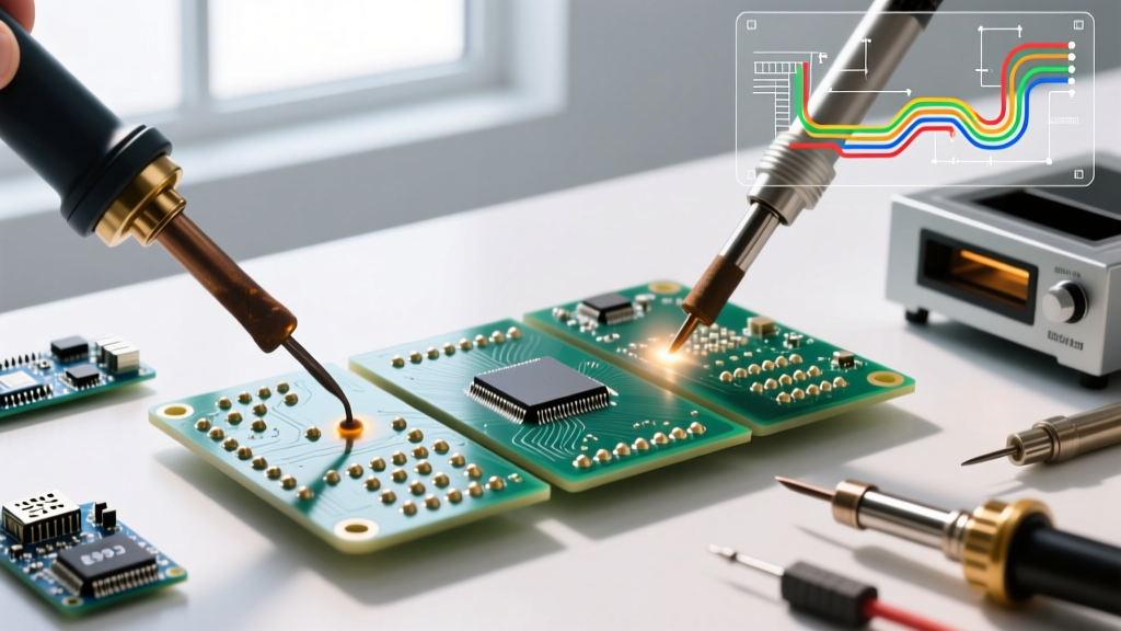
As of 2026, the transition to lead-free alloys like SAC305 (Sn96.5/Ag3.0/Cu0.5) has made achieving perfect soldering points more challenging due to higher melting temperatures (217°C) and narrower process windows. Whether you are assembling a one-off IoT prototype or a batch of motor controllers, choosing the right method to create these joints is critical. In this comprehensive comparison, we break down the three dominant methods for forming soldering points: traditional hand soldering, hot air rework, and convection reflow.
Method 1: Traditional Hand Soldering (The Artisan Approach)
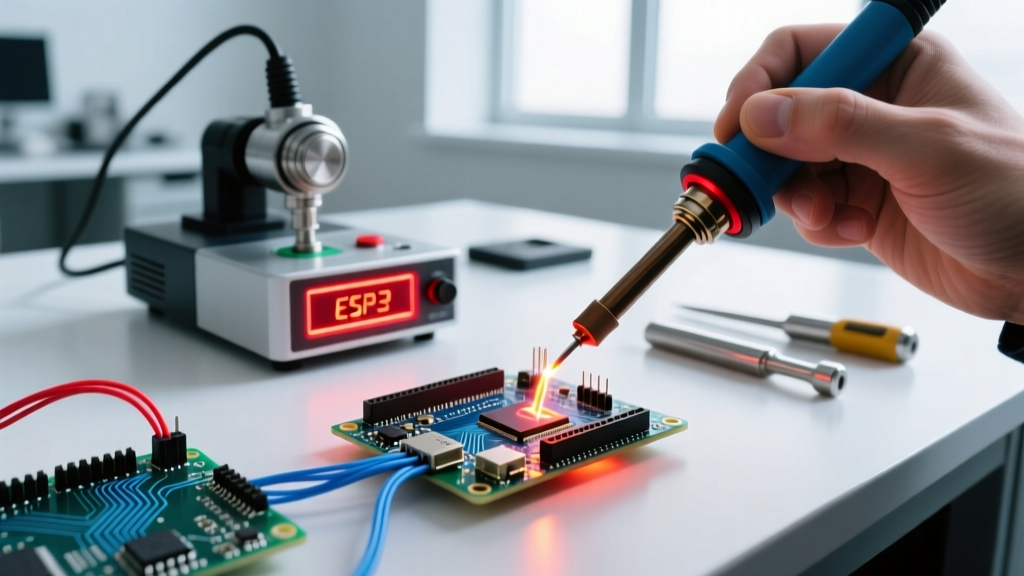
Hand soldering remains the bedrock of through-hole assembly, prototyping, and localized PCB repair. This method relies on direct thermal transfer from a heated iron tip to the component lead and PCB pad, supplemented by flux-cored solder wire.
Equipment and Thermal Dynamics
Modern soldering stations utilize closed-loop thermal feedback to maintain tip temperatures. For instance, the highly regarded Weller WE1010NA (retailing around $115 in 2026) offers rapid heat recovery, which is crucial when soldering to large ground planes that act as heat sinks. The key to creating robust soldering points by hand is selecting the correct tip geometry. A chisel tip maximizes surface area contact for heavy thermal mass joints, while a micro-conical tip is reserved for fine-pitch 0.5mm surface-mount devices (SMDs).
- Optimal Temperature: 350°C for Sn63/Pb37 (leaded); 370°C to 390°C for SAC305 (lead-free).
- Dwell Time: 2 to 4 seconds per joint. Exceeding this risks delaminating the PCB pad or degrading the component's internal die.
- Flux Dependency: Relies heavily on the rosin core within the wire. Additional ROL0 (no-clean) flux is often required for complex multi-layer boards.
Pros and Cons of Hand Soldering
The primary advantage is absolute tactile control. An experienced operator can feel the exact moment the solder wets the pad, adjusting heat input dynamically. However, the human element introduces severe variability. As noted in SparkFun's Through-Hole Soldering Guide, inconsistent dwell times and improper heat application are the leading causes of cold soldering points and disturbed joints in manual assembly.
Method 2: Hot Air Rework (The SMT Specialist)
Hot air soldering utilizes a focused stream of heated gas to simultaneously reflow solder paste applied to surface-mount pads. This method is indispensable for assembling multi-pin ICs, QFN (Quad Flat No-leads) packages, and BGAs (Ball Grid Arrays) where a traditional iron cannot reach all pads simultaneously.
Airflow vs. Temperature Profiling
Creating uniform soldering points with hot air requires balancing temperature and airflow (measured in liters per minute or CFM). The Quick 861DW, a staple in professional repair shops (priced near $265 in 2026), allows independent control of these variables. If the airflow is too high, small 0402 or 0201 passive components will literally blow off their pads before the soldering points can form. If the temperature is too low, the solder paste will not reach its liquidus state, resulting in grainy, unreliable joints.
- Optimal Settings: 380°C at 40-50% airflow for standard SMDs; reduced airflow for micro-components.
- Paste Application: Requires precision dispensing or a laser-cut stainless steel stencil to ensure uniform paste volume across all pads.
- Preheating: Using a bottom-side preheater (set to 120°C) reduces the thermal shock to the PCB and prevents board warping during localized hot air application.
Pros and Cons of Hot Air
Hot air excels at reworking and assembling dense SMD layouts without the risk of bridging adjacent pins, provided the stencil is aligned correctly. The main drawback is the steep learning curve regarding thermal profiling. Furthermore, hot air can easily scorch sensitive plastic connectors or melt adjacent soldering points if proper thermal shielding (Kapton tape) is not applied.
Method 3: Reflow Soldering (The Production Standard)
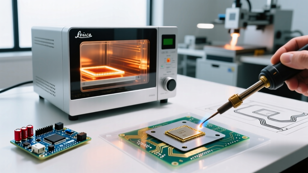
Reflow soldering is the industry standard for batch production. It involves applying solder paste via stencil, placing components using a pick-and-place machine or tweezers, and then subjecting the entire board to a carefully controlled thermal profile in a convection oven.
The Four-Stage Thermal Profile
Unlike hand soldering, where the operator manages the heat locally, reflow ovens manage the ambient environment to create hundreds of identical soldering points simultaneously. The NASA Workmanship Training manuals emphasize that strict adherence to thermal profiles is non-negotiable for high-reliability aerospace electronics. The standard profile consists of four zones:
- Preheat/Ramp: Gradual temperature increase (typically 2°C to 3°C per second) to evaporate volatile flux solvents without causing solder splatter.
- Soak (Thermal Equalization):strong> Holding the board at 150°C–180°C for 60-90 seconds ensures all soldering points, regardless of component mass, reach the same baseline temperature.
- Reflow (Liquidus): The oven spikes to 245°C–250°C (for SAC305), melting the solder and allowing capillary action to pull the molten alloy into the plated through-holes and under component leads.
- Cooling: A controlled descent to solidify the IMC layer. Rapid cooling yields a fine grain structure, enhancing the mechanical strength of the soldering points.
Pros and Cons of Reflow
Reflow yields the highest consistency and throughput. Once the profile is dialed in, every soldering point on the board receives the exact same thermal treatment. The barrier to entry is cost and space; even entry-level benchtop reflow ovens like the T-962A (often upgraded with custom firmware by the DIY community) cost upwards of $300 and require significant bench space and ventilation.
Comparison Matrix: Choosing the Right Method
| Feature | Hand Soldering | Hot Air Rework | Reflow Oven |
|---|---|---|---|
| Best Component Type | Through-hole, large SMDs, wires | QFN, BGA, dense SMD clusters | Full-board SMD assembly |
| IMC Layer Control | Low (Operator dependent) | Medium (Airflow/Time dependent) | High (Profile controlled) |
| Setup Cost (2026) | $80 - $150 | $180 - $350 | $300 - $2,500+ |
| Throughput | Very Low (1 joint at a time) | Low (1 IC/cluster at a time) | High (Entire board at once) |
| Skill Curve | Moderate (Tactile feedback) | High (Visual/Airflow management) | Low (Once profile is set) |
Common Soldering Point Defects & Method-Specific Fixes
Regardless of the method chosen, metallurgical failures can compromise the entire circuit. Understanding how defects manifest based on your chosen technique is vital for troubleshooting.
Cold Soldering Points
Characterized by a dull, grainy, and convex appearance, cold joints occur when the solder fails to reach its liquidus temperature or is disturbed during cooling. In hand soldering, this is fixed by increasing the iron temperature or using a wider chisel tip to improve thermal transfer. In reflow, it indicates an insufficient peak temperature in the oven profile.
Tombstoning (Drawbridging)
Exclusive to SMD passives (like 0603 resistors), tombstoning happens when one pad reflows before the other, and the surface tension of the molten solder pulls the component upright. This is a common hot air defect caused by uneven airflow. It is mitigated in reflow ovens by extending the soak zone, ensuring both pads reach thermal equilibrium simultaneously before the solder melts.
Solder Bridging
When soldering points merge together, creating a short circuit, it is usually due to excessive solder volume. In hand soldering, this is fixed by using a clean, fluxed wick to draw away excess alloy. In stencil-based reflow, it requires reducing the stencil aperture size by 10-15% to deposit less paste on fine-pitch IC pins.
The Role of Flux Chemistry in Joint Formation
No discussion of soldering points is complete without addressing flux. Flux removes oxidation from the copper pads and component leads, allowing the molten solder to wet the surfaces. For hand soldering, Rosin Mildly Activated (RMA) wire cores are standard. However, for hot air and reflow methods utilizing solder paste, the flux vehicle is highly complex. Modern no-clean pastes (ROL0 classification) leave behind a clear, non-conductive residue that is safe to leave on the board, whereas water-soluble pastes (ORH1) offer superior wetting for difficult surfaces like oxidized nickel but mandate rigorous ultrasonic cleaning post-reflow to prevent electrochemical migration.
Expert Verdict: Which Method Wins?
There is no single "best" method for creating soldering points; the optimal choice is dictated by your production volume and component density. For hobbyists, repair technicians, and through-hole prototyping, a high-quality hand soldering station remains unbeatable for its flexibility and low barrier to entry. If your work involves replacing multi-pin surface-mount ICs or working with hidden thermal pads, a hot air rework station is mandatory. However, if you are designing a product for commercial release and need to manufacture 50 or more boards with dense SMD layouts, investing time into stencil design and utilizing a reflow oven will yield vastly superior, IPC-compliant soldering points with a fraction of the manual labor.